2-16
Chapter2
CX6
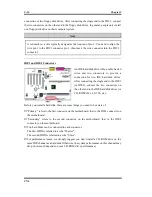
connection of two floppy disk drives. After connecting the single end to the FDC1, connect
the two connectors on the other end to the floppy disk drives. In general, people only install
one floppy disk drive on their computer system.
Note
A red mark on a wire typically designates the location of pin 1. You need to align the
wire pin 1 to the FDC1 connector pin 1, then insert the wire connector into the FDC1
connector.
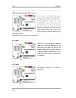
IDE1 and IDE2 Connectors
An IDE hard disk drive ribbon cable has 40
wires and two connectors to provide a
connection for two IDE hard disk drives.
After connecting the single end to the IDE1
(or IDE2), connect the two connectors on
the other end to the IDE hard disk drives (or
CD-ROM drive, LS-120, etc.).
Before you install a hard disk, there are some things you need to be aware of:
♦
“Primary” refers to the first connector on the motherboard, that is, the IDE1 connector on
the motherboard.
♦
“Secondary” refers to the second connector on the motherboard, that is, the IDE2
connector on the motherboard.
♦
Two hard disks can be connected to each connector:
The first HDD is referred to as the “Master”,
The second HDD is referred to as the “Slave”.
♦
For performance issues, we strongly suggest you don’t install a CD-ROM drive on the
same IDE channel as a hard disk. Otherwise, the system performance on this channel may
drop. (how much depends on your CD-ROM drive performance)
Содержание CX6
Страница 2: ......
Страница 13: ...Introduction of CX6 Features 1 9 User s Manual 1 3 Layout Diagram Figure 1 1 Motherboard component location ...
Страница 14: ...1 10 Chapter1 CX6 1 4 The System Block Diagram Figure 1 2 System diagram of the Intel 820 chipset ...
Страница 78: ...3 44 Chapter3 CX6 ...
Страница 84: ...B 4 Appendix B CX6 ...
Страница 90: ...D 4 Appendix D CX6 ...
Страница 96: ...E 6 Appendix E CX6 ...
Страница 104: ...G 4 Appendix G CX6 ...
Страница 110: ...H 6 Appendix H CX6 ...

