Introducing the BIOS
User’s Manual
4-27
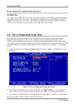
setting is
S1 (PowerOn-Suspend)
. POS is “
P
ower
O
n
S
uspend”, and STR is “
S
uspend
T
o
R
AM”.
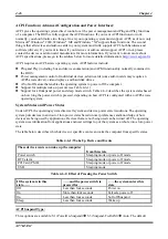
Generally, ACPI has six states: System S0 state, S1 state, S2 state, S3 state, S4 state, S5 state. S1 and S3
states are described below:
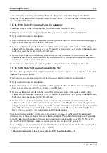
The S1 (POS) State (POS means Power On Suspend):
While the system is in the S1 sleeping state, its behavior is as described below:
The processor is not executing instructions. The processor’s complex context is maintained.
Dynamic RAM context is maintained.
Power Resources are in a state compatible with the system S1 state. All Power Resources that supply a
System Level reference of S0 are in the OFF state.
Devices states are compatible with the current Power Resource states. Only devices which solely
reference Power Resources which are in the ON state for a given device state can be in that device state.
In all other cases, the device is in the D3 (off) state.
Devices that are enabled to wake the system and that can do so from their current device state can
initiate a hardware event which transitions the system state to S0. This transition causes the processor
to continue execution where it left off.
To transition into the S1 state, the operating software does not have to flush the processor's cache.
The S3 (STR) State (STR means Suspend to RAM):
The S3 state is logically lower then the S2 state and is assumed to conserve more power. The behavior of
this state is defined as follows:
Processor is not executing instructions. The processor complex context is not maintained.
Dynamic RAM context is maintained.
Power Resources are in a state compatible with the system S3 state. All Power Resources that supply a
System Level reference of S0, S1, or S2 are in the OFF state.
Devices states are compatible with the current Power Resource states. Only devices which solely
reference Power Resources which are in the ON state for a given device state can be in that device state.
In all other cases, the device is in the D3 (off) state.
Devices that are enabled to wake the system and that can do so from their current device state can
initiate a hardware event which transitions the system state to S0. This transition causes the processor
to begin execution at its boot location. The BIOS performs initialization of core functions as required to
exit an S3 state and passes control to the firmware resume vector. Please see the ACPI Specification
Rev. 1.0 book section 9.3.2 for more details on BIOS initialization.
From the software point of view, this state is functionally the same as the S2 state. The operational
difference can be that some Power Resources that could be left ON in the S2 state might not be available
to the S3 state. As such, additional devices can be required to be in logically lower D0, D1, D2, or D3
state for S3 than S2. Similarly, some device wake events can function in S2 but not S3.
Because the processor context can be lost while in the S3 state, the transition to the S3 state requires that
the operating software flush all dirty cache to DRAM.
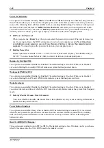
Above information for system S1 were refer to ACPI Specification Rev. 1.0.
Содержание AB-AT7-MAX2
Страница 2: ......
Страница 34: ...Chapter 2 AT7 MAX2 2 6 ...
Страница 54: ...Chapter 3 AT7 MAX2 3 20 ...
Страница 94: ...Chapter 5 AT7 MAX2 5 6 ...
Страница 98: ...Chapter 6 AT7 MAX2 6 4 ...
Страница 102: ...7 4 Chapter 7 AT7 MAX2 ...
Страница 106: ...A 4 Appendix A AT7 MAX2 ...
Страница 110: ...Appendix B AT7 MAX2 B 4 ...
Страница 114: ...Appendix C AT7 MAX2 C 4 Step 10 Now you can check the Device Manager to see that the devices are properly installed ...
Страница 118: ...Appendix D AT7 MAX2 D 4 ...
Страница 122: ...Appendix E AT7 MAX2 E 4 ...
Страница 136: ...H 4 Appendix H AT7 MAX2 ...

