


6
User’s guide VUBB
|
1ZSC000562-AAL en
2. Introduction
2.1 General
The on-load tap-changers manufactured by ABB have been
developed over a period of many years to provide maximum
reliability. In most applications, the simple and robust
design provides a service life equal to the service life of the
transformer.
Minimum maintenance is required for trouble-free operation.
Maintenance is normally not required on the parts situated
in the oil of the transformer tank. The only parts requiring
maintenance are the vacuum interrupters (which may
require replacement), the insulating oil and the motor-drive
mechanism.
WARNING
Small amounts of explosive gases are constantly
discharged from the breathing devices (dehydrating
breather or one-way breather). Make sure that no
open fires, hot surfaces or sparks are present in the
immediate surroundings of the breathing devices.
Personnel operating and inspecting the tap-changer
must have good knowledge of the apparatus and be
aware of the risks pointed out in this manual.
Personnel making electrical connections in the motor-
drive mechanism must be certified for such work.
CAUTION
After a pressure relay trip, contact ABB. The tap-
changer housing must be drained and the selector
switch lifted and carefully examined before the
transformer is reenergized.
2.2 Functional description
The on-load tap-changer is a device for changing the tapping
connection of a winding while the transformer is under load.
The main purpose is to maintain a constant voltage out from
the transformer and to compensate for variations in the load
situation. The tap-changer is connected to the transformer
via the tap winding. The main function is tap selection, which
is accomplished by changing the number of turns on the
regulating winding.
Although numerous different circuit solutions are available,
the selected solution has been found to offer the best
combination of technical performance and potential
for economic operation. By using auxiliary contacts in
combination with vacuum interrupters, the contacts are used
for carrying current and the vacuum interrupters are used
for energized switching. With this solution, only two vacuum
interrupters are required per phase.
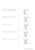
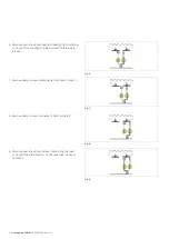
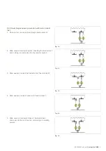
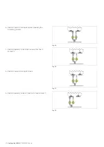
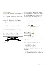
The electrical circuit principle for the VUBB is shown in
Figs. 1-18. The purpose of the operation is to commute the
load from one tap to the other in order to change the voltage.
Depending on in which direction the center shaft is rotating,
two different contact sequences are obtained – either the
main contacts operate first, or in the other direction, the
transition contacts operate first.
The figures on the following pages show the contact
sequence along with the physical position of the interrupter.
Содержание VUBB
Страница 1: ...Vacuum on load tap changers type VUBB User s guide 1ZSC000562 AAL en...
Страница 43: ......


