


1ZSC000562-AAL en
|
User’s guide VUBB
11
2.3 System overview
The implementation of vacuum technology improves breaking
capacity, increases contact life and reduces maintenance.
The design allows easy access to the function control for the
switching sequence.
The VUBB tap-changer is of the in-tank design. The motor-
drive mechanism is attached to the transformer tank and
connected to the tap-changer by means of drive shafts and
a bevel gear. The motor-drive mechanism is not described in
this manual.
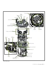
The tap-changer is mainly comprised of a housing, a
mechanical drive system, a change-over selector and a
selector switch.
The tap-changer is designed so that it is suitable for both
cover mounting and yoke-mounting (pre-mounting on the
transformer’s active part).
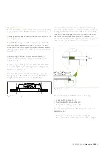
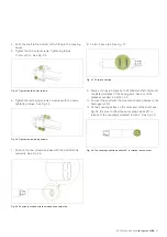
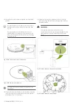
Cover-mounting means that the tap-changer is lowered
through a hole in the transformer cover and then bolted
straight onto the transformer cover. See Fig. 19.
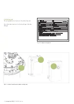
Yoke-mounting means that the tap-changer is temporarily
placed on a fork located on the active part of the transformer.
See Fig. 20. The transformer cover is then lowered onto the
tank, and the tap-changer is lifted and bolted to the cover.
Yoke-mounting allows the transformer manufacturer to
connect the windings to the tap-changer before drying and
without having the transformer cover mounted.
Fig. 19. Cover-mounting.
Fig. 20. Yoke-mounting.
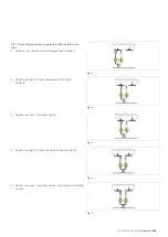
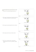
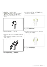
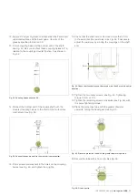
The tap-changer type VUBB can be switched using:
– Linear switching, see Fig. 21.
– Plus/minus switching, see Fig. 22.
– Coarse/fine switching, see Fig. 23.
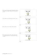
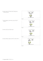
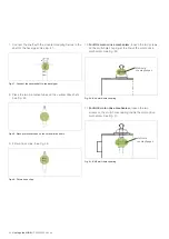
The general arrangement of a tap-changer system can be
executed using:
– Three-phase, star point connection, see Fig. 24.
– Three-phase delta, fully insulated connection, see Fig. 25.
15 mm
Содержание VUBB
Страница 1: ...Vacuum on load tap changers type VUBB User s guide 1ZSC000562 AAL en...
Страница 43: ......


