


1ZSC000562-AAL en
|
User’s guide VUBB
25
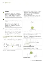
12. Apply a thin layer of grease to all spherical shaft ends and
unpainted surfaces of the bevel gears. Use any of the
greases specified in Section 3.3.
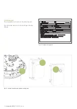
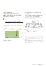
13. Fit two coupling halves at the bottom end of the shaft;
see Fig. 43. Be sure to offset these coupling halves 90° in
relation to the couplings mounted in step 2 as shown in
Fig. 52.
Fig. 52. Coupling halves offset by 90°.
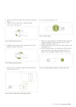
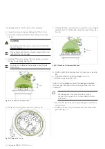
Fig. 53. Connect the square shaft to the motor-drive mechanism.
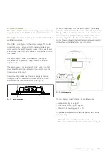
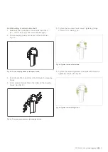
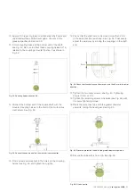
Fig. 54. Check that the shaft cannot be moved more than 2 mm in the axial
direction.
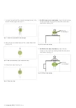
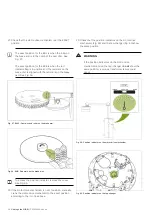
Fig. 55. Place the protective tube with the greater diameter upwards.
14. Connect the bottom end of the square shaft with the
mounted coupling halves to the shaft of the motor-drive
mechanism. See Fig. 53.
15. Fit six screws and washers in the holes on the coupling
halves (see Fig. 44) and tighten them lightly.
16. Check that the shaft cannot be moved more than 2 mm
in the axial direction (axial play). See Fig. 54. If necessary,
adjust the axial play by moving the couplings on the shaft
end.
17. Tighten the two outer screws; see Fig. 45. Tightening
torque 10 Nm ±10 %.
18. Tighten the remaining screws crosswise (see Fig. 46) with
the same tightening torque.
19. Place the protective tube with the greater diameter
upwards, facing the bevel gear. See Fig. 55.
20. Secure the tube with a hose clip. See Fig. 56.
Fig. 56. Fit a hose clip.
2 mm
Содержание VUBB
Страница 1: ...Vacuum on load tap changers type VUBB User s guide 1ZSC000562 AAL en...
Страница 43: ......


