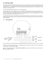
Operating instruction manual
| TX Thermal Disperson Level Switches 13
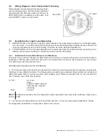
Wiring diagram for dual compartment housing (alumi-
num and stainless steel). With the dual compartment
housing option and /DS option there will only be one
SPDT switch (form C) available for each board. (You
lose the DPDT function on each board.)
5.2 Wiring Diagram - Dual Compartment Housing
5.3 Installation for Liquid Level Operation
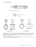
A. SIDE MOUNTED—The instrument can be mounted directly to the vessel being monitored or in a standpipe paral-
lel to the vessel. It is recommended that the probe extend into vessel/stand pipe in highly viscous products. This
is best accomplished by using a half-coupling or thread-o-let for the standard threaded unit.
B. TOP MOUNTED—For top mounted installation it is recommended that the electrical/conduit connection be iso-
lated by such means as a potting Y so that moisture can not enter the housing.
5.3.1 Installation for Flow Rates (Minimum and Maximum)
This switch can be also be configured to detect between a minimum or a maximum flow rate or a minimum/maximum
temperature. With the dual circuit board option the unit can also detect a flow rate and temperature in one housing.
The output relays would be wired in series.
PROCEDURE FOR LIQUID LEVEL OPERATION
A. The instrument detects the thermal conductivity of the medium surrounding the probe and therefore can detect the
interfaces of many different mediums. The following list is provided to give examples of typical thermal conductivity of
different mediums. Refer to “wet” as a medium with a relatively “good” thermal conductivity and “dry” as a medium that
has a relatively “poor” thermal conductivity.
B. “OK”
air or gas
foam
granular solids & powders
hydrocarbons / organics
emulsions
“Best”
aqueous
NOTE:
The thermal conductivity of a clear liquid will be better compared to the same liquid containing a high concen-
tration of solids.
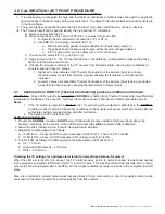
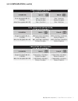
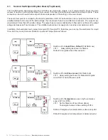
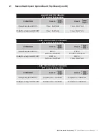
C. The instrument is factory default is set for liquid flow detection. For level or temperature applications, change
the configuration as detailed in “configuration” earlier in the manual.
mV output
24-28 VDC

