4 TX Thermal Disperson Level Switches |
Operating instruction manual
2.0 EXPLANATIONS
The TX Thermal Dispersion switch has two RTD elements, one of which is heated by a small, low wattage electric
heating element. The thermal dispersion switch operates on the principle of a difference in thermal conductivity (TC)
between mediums (air/vapor vs. liquid or high vs. low flows of air, vapor or liquid). Once the switch has stabilized in
any given process condition, it can be adjusted such that a change (increase or decrease) in the amount of heat con-
ducted away from the heated RTD (thermal dispersion) due to a change in thermal conductivity of the process at the
sensors will cause the acative (heated) RTD to change in temperature (resistance). This change may be an increase
in temperature due to a decrease in Thermal Conductivity (TC) or a decrease in temperature due to an increase in TC.
This change is detected by the TX switch module.
This approach to calibrating the TX thermal conductivity switch may be more easily understood than the preceding
methods presented.
Understanding Switch Function:
1.
An increase in flow, be it gas or liquid, or a change from gas to liquid at the sensor causes
more
heat to be con-
ducted away from the heated element, due to an
increase
in thermal conductivity at the sensor and a resultant
decrease in the “heated” element’s temperature.
The TX recognizes this change as a decrease in the differ-
ential temperature between the two RTD sensors.
2.
A decrease in flow or a change from liquid to a gas or vapor at the sensor results in
less
heat being conducted
away from the heated element (RTD) due to a
decrease
in thermal conductivity at the sensor and a resulting
increase in the “heated” element’s temperature.
The TX recognizes this change as an increase in the differ-
ential temperature between the two RTD sensors.
3.
A decision needs to be made regarding the failsafe operation required by the process control system. If fail safe
is to be incorporated, the output relay and green LED should be energized at what is determined as the normal
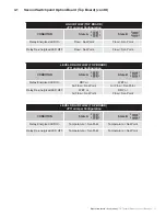
condition. JP3 jumpers are used to determine the relay action vs. the normal process condition. See the table on
page 6.
4.
JP3 jumpers can be either in a vertical position (State A) or a
horizontal position (State B)
– see page 6.
Failsafe “State” required (A or B) Setting JP3 Jumpers
See page 6 to determine the JP3 relay state (A or B) jumper settings required, considering fail safe requirements of
the process. It is generally desired to have the green LED and the output relay energized with the normal process
condition at the sensor, providing an alarm should power be lost to the TX switch. Set JP3 jumpers according to the
particular application.
State A
– Green LED and output relay are
energized
at High Thermal Conductivity
(
Low
sensor
Delta T) process
condition – high level, high flow (process conditions are above set point).
State B
– Green LED and output relay are
energized
at Low Thermal Conductivity
(
High
sensor
Delta T) process
condition – low level, low flow (process conditions are below set point).
Relay State A – State B definitions (restated)
State A -
The green LED and output relay are
energized
when the sensor is in the higher Thermal Conductivity (lower
differential temperature) condition. Normal process conditions for Fail Safe operation. Flow is > set point; Level is
above the sensor. The green LED and output relay are
de-energized
when the sensor is in the lower Thermal Conduc-
tivity (higher differential temperature) condition. Alarm process conditions for Fail Safe operation. Flow is < set point;
Level is below the sensor.
State B -
The green LED and output relay are
energized
when the sensor is in the lower Thermal Conductivity (higher
differential temperature) condition. Normal process conditions for Fail Safe operation. Flow is < set point; Level is
below the sensor. The green LED and output relay are
de-energized
when the sensor is in the higher Thermal Con-
ductivity (lower differential temperature) condition. Alarm process conditions for Fail Safe operation. Flow is > set
point; Level is above the sensor.

