Operating instruction manual
| TX Thermal Disperson Level Switches 11
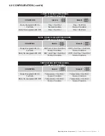
LIQUID FLOW (TOP BOARD)
JP11 Jumper Configuration
CONDITION
State A
State B
Relay Energized LED On
Flow < Set-Point
Flow > Set-Point
Relay De-energized LED OFF
Flow > Set-Point
Flow < Set-Point
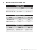
LEVEL OR AIR FLOW (TOP BOARD)
JP11 Jumper Configuration
CONDITION
State A
State B
Relay Energized LED On
DRY or
Air Flow < Set-Point
WET or
Air Flow > Set-Point
Relay De-energized LED OFF
WET or
Air Flow > Set-Point
DRY or
Flow < Set-Point
LEVEL OR AIR FLOW (TOP BOARD)
JP11 Jumper Configuration
CONDITION
State A
State B
Relay Energized LED On
Temperature > Set-Point
Temperature < Set-Point
Relay De-energized LED OFF
Temperature < Set-Point
Temperature > Set-Point
4.1 Second Switchpoint Option Board (Top Board) (cont’d)
1
3
2
4
2
4
1
3
1
3
2
4
2
4
1
3
1
3
2
4
2
4
1
3

