30
NOTE:
All 4 Vents MUST be open. Position Vent tubing in a downward direction
so that moisture does not accumulate in the tubing. Vent lines DO NOT
need to be extended outside of CWE.
XVIII.
CWE Optional Catalytic Heater Installation
The following procedures describe the steps for installing a Catalytic Heater for the Cold
Weather Enclosure.
A. Materials
•
Catalytic Heater (installed at factory)
•
Thermostat Assembly with Temperature Probe
•
Regulator Assembly W/ Shut-off
•
T
Assembly
•
Tubing
•
Temperature Probe Mounting Clip
•
Teflon
Tape
•
¼” male pipe connection from External gas source to Catalytic Heater. Materials
for gas source is not be provided by Totalflow. Quantities and materials to be
determined by the technician based on installation and local codes.
•
DC Power source wiring. Materials for external Power source for Electrical
Preheat wiring not provided by Totalflow. Quantities and materials to be
determined by the technician based on installation and local codes.
B. Instructions
1)
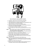
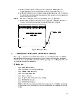
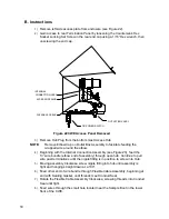
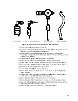
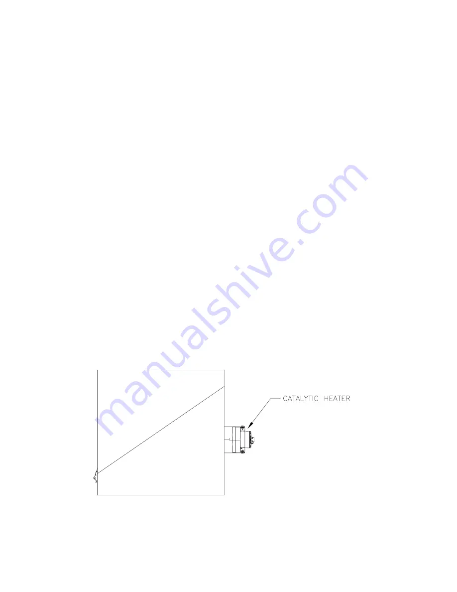
Locate the installed Catalytic Heater on the rear of the Cold Weather
Enclosure (see Figure 36).
2)
Remove protective end cap from Catalytic Heater input fitting if required.
Figure 36 Catalytic Heater Option in Cold Weather Enclosure

