


34
SensyMaster FMT230, FMT250
THERMAL MASS FLOWMETER | OI/FMT230/250-EN REV. C
… 6 Installation
… Assembly of the welding adapter with compression ring fitting
First installation of the sensor
When mounting the sensor, a distinction is made between
first
installation
and reinstallation. We will address
first installation
below.
Please also follow the ‘An Installer’s Pocket Guide for Swagelok®
Tube Fittings – MS-13-151.pdf’ available at
www.swagelok.de/en
.
Required tools
• Open-end wrench, width across flats 35 mm (1
⅜
in)
• Open-end wrench, width across flats 38 mm (1½ in)
• Caliper gage or comparable measurement tool
• Marker pen (permanent marker) for marking
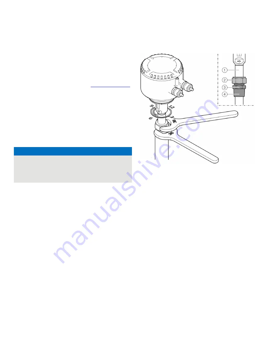
Description of first installation
1. Carefully insert the prepared sensor into the welding
adapter.
NOTICE
Damage to the device
Mechanical damage to the sensor element can occur due to
improper installation.
• When inserting into the welding adapter, the sensor
protection frame must not hit the bottom of the piping.
2. Screw in the compression fitting (with thread sealing
compound) into the welding adapter, first by hand and then
tighten with 1.5 to 2.5 turns.
3. Move the sensor to the correct height for the calculated ‘Z’
dimension (see Figure 22) and secure the compression fitting
against shifting by tightening the union nut by hand.
4. Align the sensor such that the lateral flow arrow on the upper
sensor protection tube end points in the exact direction of
the flow.
5. Using a suited marker pen, mark the orientation and height
of the sensor on the sensor protection tube, compression
fitting and the welding adapter (see Figure 23, pos.
3
).
The marking on the union nut is also used as a starting
position (6 o’clock position, see Figure 24) for the tightening
of the compression fitting
1
Sensor protection tube
2
Union nut
3
Fitting body
4
Thread
Figure 24: Tighten sensor
6. Using an open-end wrench, hold the fitting body in position
and with another open-end wrench, tighten the union nut by
1¼ turns clockwise to the 9 o’clock position.
In the process, check the orientation of the sensor with the
help of the markings and correct as needed.
To achieve maximum measuring accuracy, the ‘Z’ dimension
must be set with a tolerance of ±2 mm (±0.08 in) during
installation of the sensor.
Note
Before commissioning, the tightness and compressive strength
of the measuring point must be guaranteed!
• In addition, check the fittings using a suited leak detection
spray.


