


Installation and operating instruction |
SafeRing/SafePlus 36kV 19
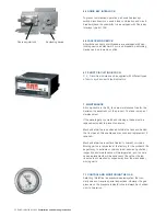
Blown fuse
indicator
5.3 INSTALLATION AND REPLACEMENT OF FUSE LINKS
The F-module is equipped with a blown fuse indicator. If this
indicator changes colour from white to red, this means that at
least 1 fuse-link has blown. This will also automatically trip all
three phases of the switch-fuse disconnector. It also makes
operation of the switch-disconnector impossible before the
blown fuse-link(s) has been replaced.
Acc. to IEC 60282-1 it is advisable to replace all 3 fuse-links
even if only 1 or 2 has blown.
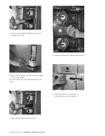
Fuse-links are replaced as shown in the sequence of illustra-
tions.
Switch-fuse combinations are supplied without fuse-links
installed.
When installing fuse-links, follow the sequence of illustrations
1-9.
1. Before entering handle on to earthing switch, press
interlocking bracket towards left.
2. Close earthing switch by turning operating handle
clockwise..
3. Turn knob anticlockwise and tilt out front cover
to gain access to fuse canisters.
4. Pull handle and open the fuse canister.