


25
Terminals
and wiring
The screw terminal to facilitate all input and
output connections are located on the rear panel
of the annunciator case. Each screw terminal
can accommodate one or two max. 2.5 mm
2
wires. No terminal lugs are needed.
Six terminals are used for connecting the
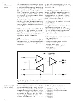
SPA-bus. The connection cable for the fiber
optic SPA-ZC module is attached to these ter-
minals.
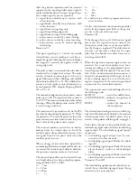
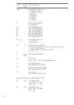
In an independent system the group alarm No
15 can be programmed for internal fault super-
vision and the group alarm No 16 for audible
alarm. The programming is made by changing
the jumper position on connector X44. The con-
nector is located on the left side of the mother
PC-board, seen from the rear.
Function
Jumper
position X44
Group alarm output 15
Pin 1-2
Group alarm output 16
Pin 4-5
Output for audible alarm
Pin 5-6
Output for internal supervision Pin 2-3
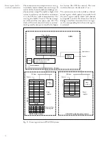
At an internal fault the relay output contact
opens. A closing function is obtained by res-
oldering a jumper on input/output module
SWIM 2A1. The module is accessible after re-
moving the annunciator module No. 4 to the
right.
WARNING!
Although the supply voltages are switched off
the output contacts on the input/output mod-
ule concerned may contain external voltages.
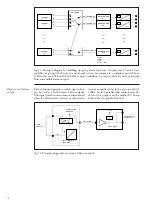
The two boards can be separated from each
other by pressing the snap-locks on the spacers
and then separate them. The programming
jumpers on the relay card are numbered as fol-
lows:
W1 = group alarm 13
W2 = group alarm 14
W3 = group alarm 15/internal fault
W4 = group alarm 16/audible alarm
The programming is made by moving the
jumper for the concerned relay as illustrated in
the printed scheme on the PC-board, so that
the required contact function is achieved. The
relay function of the other outputs are repro-
grammed in the same way. Every input/output
module includes four relays.
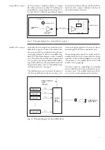
The alarm channels 63 and 64 can be repro-
grammed to local/remote inputs. Then the
channels 63 and 64 will operate as position in-
dicators for the local/remote switch and are to
be programmed for signal following indication
(S4 = 2). The programming is made by chang-
ing the position of a jumper on connector X45.
The connector is found to the left on the mother
PCB, seen from the rear.
Function
Jumper
position X45
Alarm channel 63
Pin 1-2
Alarm channel 64
Pin 4-5
Local position (channel 63)
Pin 2-3
Remote position (channel 64)
Pin 5-6