


16
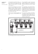
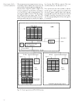
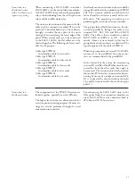
Fig 13. Principle diagram for building up group alarm functions. Output relay 15 and 16 are
available for group reflash only in a multi rack system, for instance in a combination with Saco
128R4 relay rack. When SACO 64D4 is used standalone the output relays are used as internal
fault and audible alarm outputs.
CHANNEL
1
CHANNEL
2
A
B
A
B
S5
S6
1
S5
S6
2
GROUPING
REFLASHMODE
S1
REFLASHMODE
S2
S5
S6
16
CHANNEL
16
A
B
REFLASHMODE
S16
0 = VSJ
1 = MSJ
2 = PJ
3 = VSJ + ISR
GROUPALARM 16
GROUPALARM 1
GROUPALARM 2
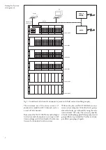
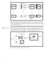
Field contact follower
output
Each alarm input provides a control signal which
can be used as a field contact follower signal.
The signal which is instantaneous and activated
when the field contact is closed, can be used to
control an auxiliary relay in the relay unit SACO
128R4. Four 16-pole flat cable contacts are avail-
able for this purpose on the mother PC-board
behind the rear panel of the rack.
FLAT CABLE
+ 24 V
SACO 128R4
FIELD CONTACT
FOLLOWER
TO THE ALARM
MODULES
SACO 148D4 OR
SACO 64D4
48 V
FIELD
CONTACT
0V
Fig 14. Principle diagram for a contact follower output.