ABB saco 64D4 Скачать руководство пользователя страница 15

15

Auxiliary outputs

The annunciator includes 16 auxiliary output
relays. 14 output relays act as group alarm reflash
output elements, one auxiliary output relay is
dedicated for control of an audible device and
one relay acts as an auxiliary output element for
the internal self-supervision function. In a cen-
tralized system (i.e. when several SACO 64D4
are connected together) there might be no need
to use the audible sevice output and the
selfsupervision output on every unit separately,
hence all 16 outputs can be used as Group Alarm
Reflash outputs.

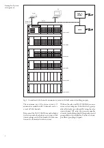
By using the relay unit SACO 128R4, which
may accommodate a total of 128 output relays,
and which is connected to the annunciator
modules  by means of flat cables, a total of 16
reflash group outputs, 16 contact doubler out-
puts and 16 paralell lamp outputs can be pro-
vided from each annunciator module. These
outputs can also be grouped by means of the
grouping module SACO 64C5
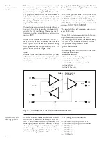
Group alarm reflash
signals

Each alarm channel generates two reflash out-
put signals, A and B, which can be freely linked
to the reflash output relays to form group alarm
reflash functions. The group alarm reflash out-
put relays can be given one of the following
modes of operation selectable by programming,
separately for both of the output relays:
0 = FCFR, Field Contact Following Reflash
1 = AACR, Acknowledge Action Controlled

Reflash

2 = ISR, Impulse Shaping Reflash
3 = FCFR + ISR, Field Contact Following

Reflash with a 300 ms interruption of the
reflash signal any time a new alarm signal
joins in an already active group alarm bunch

4 = FCFR + AACR, Field Contact Following

Reflash and Action Controlled Reflash (se
figure below)

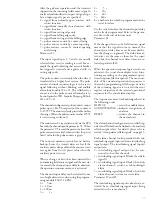
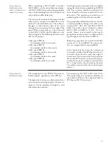
Parameter  S1…S16 (Module related settings)

Channel input delays

Channel reset delay

Alarm 1

Alarm 2

Acknowledge

Signal following

Alarm memory following 

Pulse type 

Signal following with break   

FCFR + AACR

Fig. 12. Principle diagram for the different reflash signal types. The alarm signals 1 and 2 are
grouped to the same group alarm reflash signal.

NOTE!
The reflash signals are always accompanied by
a certain basic delay. The basic delay time de-
pends on the number of incoming alarm sig-
nals per time unit and on the number of inter-

nal interlocking levels in use. The basic time
delay of the reflash signal is 70 ms if only one
alarm signal is received within a time period of
200 ms and if no interlockings are used.

Содержание saco 64D4

Страница 1: ...PROGRAM 1 2 3 4 5 6 7 8 9 10 11 12 13 14 15 16 TEST RESET ACK SILENCE FAULT ON PROGRAM 1 2 3 4 5 6 7 8 9 10 11 12 13 14 15 16 FAULT ON PROGRAM 1 2 3 4 5 6 7 8 9 10 11 12 13 14 15 16 FAULT ON PROGRAM 1 2 3 4 5 6 7 8 9 10 11 12 13 14 15 16 SACO 16D2 SACO 16D2 SACO 16D2 SACO 16D2 ...

Страница 2: ...Example of channel interlocking configuration 19 Serial communication interface 20 Synchronizing of the blinking sequence 20 Parameterization 21 Auxiliary power supply system 21 Self supervision output 22 Application 23 Mounting 23 Connection diagram 24 Terminals and wiring 25 Mounting and connection of acknowledge module SWDM 3A1 26 Connection to a distributed system with or without event sequenc...

Страница 3: ...d as a stand alone unit or combined with other SACO 64D4 subracks as a pure signalling system Further more it can be integrated into an event sequence reporting and signalling system In such a case the units communicate with each other over a serial interface and the so called SPA bus or LON bus allowing a geographi cally distributed configuration of the units Serial communication contact with a s...

Страница 4: ...ector included in the unit These outputs can be uti lized by means of the relay unit SACO 128R4 which can hold up to eight 16 channel output auxiliary relay cards The serial interface connection to the SPA bus or LON bus is made either by means of a flat cable connector between subracks or fiber op tic connection modules connected to the screw terminals The former alternative is used for uniting u...

Страница 5: ...dia the following values can be given plastic fibre at least 30 m glass fibre at least 1 km pairs of twisted conductor without galvanic isolation at least 30 m pairs of twisted conductor with galvanic iso lation at least 200 m Fiber optic media is always recommended due to its good resistance to electromagnetical in terference The setting values groupings and interlockings of the annunciator modul...

Страница 6: ...e markings can be listed and or the informa tion can be forwarded to other systems Without the relay unit SACO 128R4 the annun ciator system comprises 16 builtin freely group able reflash relays per subrack By using the relay unit with max 128 relays the necessary number ofcontactmultiplyings parallellampoutputs and group reflashes is provided for Further each out put allows grouping of signals RS...

Страница 7: ... The annunciator modules can be connected to the control data communicator by means of fibre optic loops The individual units are self contained and provided with outputs in the same way as a centralized system The reflash grouping for the entire system is made on out put contact level MicroSCADA SPA ZC 21 SPA ZC 21 SPA ZC 21 SPA ZC 22 SPA ZC 21 SPA ZC 21 SPA ZC 21 SPA ZC 21 SACO 64D4 SACO 64D4 SA...

Страница 8: ... PC board The mother PC board also contains the card connectors for the plug in modules and the wiring for the inputs and outputs The rack housing the modules is a 19 inch so called Euro rack with a height of 3 U about 133 mm When mounting several SACO 64D4 subracks together or combining them with other SPACOM subracks a space of 1 U i e about 44 mm should be left between the subracks The subrack ...

Страница 9: ...tively the setting can be made by using a portable programming module type SACO 16PM All setting values are stored in non volatile EEPROM type memories Alternatives for acknowledgement and resetting By means of separate push buttons via exter nal acknowledge inputs The push buttons in the acknowledge mod ule SWDM 3A1 via external acknowledge in puts The acknowledgemodule SWDM 3A1 is if in cluded l...

Страница 10: ...supply module 0 V 48 V Field contact Galvanic isolation Fig 7 Principle of alarm channel input Alarm channel functions An alarm channel is composed of a number of functional blocks illustrated below The lists of variables underneath some of the blocks indi cate that a certain parameter can be selected from a set of given values i e the parameter can be programmed The selected parameter is shown in...

Страница 11: ...on the operation sequence memory is activated The channel input delay can be selected from a set of eight alternative values using the program ming module SACO 16 PM 0 5 ms 1 20 ms 2 100 ms 3 1 s 4 5 s 5 20 s 6 60 s 7 160 s 8 another value which is programmed via the serial interface Via the serial interface the channel input delay can be freely programmed Refer to the param eter list in the end o...

Страница 12: ...tional sequences are 0 ISA A automatic reset 1 ISA A 1 automatic reset separate reset of audible alarm 2 ISA M 1 manual reset separate reset of au dible alarm 3 ISA R 1 manual reset separate reset of au dible alarm visual ringback on return 4 DIN 19235 manual reset after return to normal if acknowledged while alert visual ringback on return if acknowledged before return to normal Parameter S17 The...

Страница 13: ...ntact Visual alarm indicator Acknowledge Reset of audible output Silence Audible output Reset Field contact Visual alarm indicator Acknowledge Reset of audible output Silence Audible output Reset Automatic reset separate reset of audible output ISA A 1 Manual reset separate reset of audible output ISA M 1 Manual reset visual ringback and separate reset of audible output ISA R 1 Manual reset visual...

Страница 14: ...r unit also includes a channel matrix register which operates in parallel with the event register and in which each channel corresponds to one bit If a channel is activated during an overflow situation of the even regis ter the corresponding bit in the matrix register is activated Overflow Overflow Time Slave Channel Code 2 1 500 Adding of users text Event register Clock SPA bus Synchronization SR...

Страница 15: ... to form group alarm reflash functions The group alarm reflash out put relays can be given one of the following modes of operation selectable by programming separately for both of the output relays 0 FCFR Field Contact Following Reflash 1 AACR Acknowledge Action Controlled Reflash 2 ISR Impulse Shaping Reflash 3 FCFR ISR Field Contact Following Reflash with a 300 ms interruption of the reflash sig...

Страница 16: ... VSJ 1 MSJ 2 PJ 3 VSJ ISR GROUPALARM 16 GROUPALARM 1 GROUPALARM 2 Field contact follower output Each alarm input provides a control signal which can be used as a field contact follower signal The signal which is instantaneous and activated when the field contact is closed can be used to control an auxiliary relay in the relay unit SACO 128R4 Four 16 pole flat cable contacts are avail able for this...

Страница 17: ...larm channel has been programmed for a sequence providing a field contact follow ing visual indication only no audible alarm will be generated please refer to Standardized op erational sequences on page 12 The audible device can be silenced by means of the silence push button or by means of an exter nal control signal applied to the remote silence control input 128 of the annunciator unit An incom...

Страница 18: ... stamp for the event register The interlockings are distributed between the different channels via eight internal interlock ing lines see figure on page 19 In addition the first four interlocking lines can be used for trans mitting blocking signals between the annuncia tor modules Each channel can be connected to two inter locking lines This means that alternatively both the interlocking inputs of...

Страница 19: ...0 S7 S9 CHANNEL 3 S8 S10 S7 S9 CHANNEL 4 S8 S10 S7 S9 CHANNEL 5 S8 S10 S7 S9 CHANNEL 6 S8 S10 S7 S9 CHANNEL 7 S8 S10 S7 S9 CHANNEL 8 S8 S10 S7 S9 CHANNEL 9 S8 S10 S7 S9 CHANNEL 10 S8 S10 S7 S9 CHANNEL 11 S8 S10 S7 S9 CHANNEL 12 S8 S10 S7 S9 CHANNEL 13 S8 S10 S7 S9 CHANNEL 14 S8 S10 S7 S9 CHANNEL 15 S8 S10 S7 S9 CHANNEL 16 S8 1 S10 2 S7 S9 CHANNEL 17 S8 S10 S7 S9 CHANNEL 18 S8 S10 S7 S9 CHANNEL 19 ...

Страница 20: ...V2 5 34 SPACOM 2 EN1 and the LON Talk proto col is described in the document LON bus LON Works network in protection and control systems 1MRS750035 MTD EN The speed of the serial communication is nor mally 9600 bits s Through the serial communication the follow ing information is read from the unit the event registers including the time markings the state of the channels and of the system the prog...

Страница 21: ... operates with one supply voltage too but in such a case the signal contact of the internal fault relay closes A supply module op erating with one supply voltage without pro viding a signal for internal system fault is avail able on request AUXILIARY SUPPLY 1 AUXILIARY SUPPLY 2 2 A SWSM 220A220 2 A SWSM 220A48 4 A FIELD CONTACT SUPPLY 48 V DC INTERNAL SUPPLIES 8 V DC 12 V DC 24 V DC Fig 20 Princip...

Страница 22: ...ibed above If a fault occurs in the 48 V DC field contact voltage generated by the annunciator unit the FAULT LED is switched on and the self super vision auxiliary output relay drops off normally energized The fault information can be sent over the serial communication If the control voltage of the auxiliary output relays disappears the self supervision auxiliary output relay drops off Self super...

Страница 23: ... or when using SACO 64D4 sub racks together with other subracks of the SPACOM series a space of 1 U about 44 mm should be left between the subracks For this purpose 2 spacers type SWSC 20 are included in every SACO 64D4 delivery The spacers al low several annunciator units to be built together to a mechanical unit 365 265 25 311 38 450 465 0 5 272 8 215 7 171 3 139 5 0 95 1 450 465 0 5 483 465 6 8...

Страница 24: ...4 73 CH1 CH9 CH2 CH3 CH4 CH5 CH6 CH7 CH8 CH10 CH11 CH12 CH13 CH14 CH15 CH16 72 71 70 69 68 67 66 65 64 63 62 61 60 59 58 57 56 55 54 53 52 51 50 49 CH17 CH25 CH18 CH19 CH20 CH21 CH22 CH23 CH24 CH26 CH27 CH28 CH29 CH30 CH31 CH32 48 47 46 45 44 43 42 41 40 39 38 37 36 35 34 33 32 31 30 29 28 27 26 25 CH33 CH41 CH34 CH35 CH36 CH37 CH38 CH39 CH40 CH42 CH43 CH44 CH45 CH46 CH47 CH48 24 23 22 21 20 19 18...

Страница 25: ...e right WARNING Although the supply voltages are switched off the output contacts on the input output mod ule concerned may contain external voltages The two boards can be separated from each other by pressing the snap locks on the spacers and then separate them The programming jumpers on the relay card are numbered as fol lows W1 group alarm 13 W2 group alarm 14 W3 group alarm 15 internal fault W...

Страница 26: ...ed to the other units over flat cables SWIR 24 28 depending on the number of racks S1 S2 S3 S4 128 129 130 131 132 Field contact voltage 48V Audible alarm reset Acknowledge Reset Annunciator module test Fig 25 Connection diagram for the acknowledge module The acknowledge module SWDM 3A1 is mounted in place of the cover plate in front of the voltage supply module The five connection cables are brou...

Страница 27: ...ing instructions are packed together with the extension module The group alarm reflash functions can be con nected in parallel by fitting a flat cable to the terminals X21 X22 X23 and X24 of SACO 64D4 The cable is then extended to another SACO 64D4 or 148D4 to its X21 X24 ter minals From a system united in this way 16 group alarm output contacts are obtained The type designation of the cable is SW...

Страница 28: ...tput Mother PC board terminals X17 X18 X19 and X20 Group alarm outputs Mother PC board terminals X21 X22 X23 and X24 The upper protective grille sheet and the rear panel have cutouts for taking outthe flat cables Start up When the auxiliary supply voltage is connected all active alarm channels are indicated as already being acknowledged These alarms are not to be found in the event register Operat...

Страница 29: ...ing ink pen or a typewriter Together with the an nunciator unit a sheet of drawing film compris ing three legend plates is delivered The channel text surface comprises 20 mm x 20 mm and the text area is ruled with four lines NOTE The starting point for the first line of the chan nel legend text is intended a few millimeters from left in order not to cover the visual LED indicator of the channel FA...

Страница 30: ... of the alarm indica tors The identification number of the module can be marked in the square in the bottom right corner of the legend plate Signalling and reporting functions Under normal conditions when no annuncia tor channels are alert and all acknowledgements have been made only the green ON indicators on the fronts of the annunciator modules are illuminated When a field contact signal is rec...

Страница 31: ... 3 group 3 4 group 4 5 group 5 6 group 6 7 group 7 8 group 8 0 interlocking output 1 channel reflash A interlocked 2 channel interlocked 3 channel interlocked not grouped 1 group 1 2 group 2 3 group 3 4 group 4 5 group 5 6 group 6 7 group 7 8 group 8 Group alarm number Type of reflash relay function 01 group alarm relay 1 02 group alarm relay 2 16 group alarm relay 16 0 field contact following 1 a...

Страница 32: ... Channel indication Group Interlock Type of interlocking Interlocking group Channel reflash A Channel reflash B Type of interlocking Interlocking group Interlock funct 1 Interlock funct 2 Output Group alarm number Type of reflash relay function Module Unit identification number Sequence Serial communication Fig 31 Parameter chart ...

Страница 33: ...nel 8 __ Function 1 Function 2 Channel 9 __ Function 1 Function 2 Channel 10 __ Function 1 Function 2 Channel 11 __ Function 1 Function 2 Channel 12 __ Function 1 Function 2 Channel 13 __ Function 1 Function 2 Channel 14 __ Function 1 Function 2 Channel 15 __ Function 1 Function 2 Channel 16 __ Function 1 Function 2 TYPE OF INTERLOCKING 0 interlocking output 1 reflash A interlocking inpu 2 channel...

Страница 34: ...s a result when parameter A is read out 0 both alarm and status channels are printed out 1 only alarm channels are printed out 2 no out printing S19 0 Pumping supervision output relay 00 not connected 01 output relay 1 02 output relay 2 16 output relay 16 S33 48 0 Control of the output relay 1 16 over the SPA bus 0 not active 1 changing of state on off 2 pulse activation S49 64 0 Pulse length of o...

Страница 35: ...nd 4 active FFFF all 16 channels active V51 Status information of the overflow matrix register HEX coded form 0000 no active channels 0001 channel 1 active 0002 channel 2 active 0003 channel 1 and 2 active 0004 channel 3 active 0005 channel 1 and 3 active 0006 channel 2 and 3 active 0007 channel 1 2 and 3 active 0008 channel 4 active 0009 channel 1 and 4 active 000A channel 2 and 4 active 000B cha...

Страница 36: ... 8 O1 16 Sate of output relay 1 16 0 not active state 1 active state C 0 Status information of module 0 when read normal state when written resets the status register 1 CPU reset has occurred 2 overflow of the event register has occurred 3 1 2 F SACO Type designation of module 16D2B T Time setting 0 000 59 999 time in seconds and milliseconds L Event sequence register Time channel and event code B...

Страница 37: ... 2 S6 0 Channel reflash B 0 not connected 1 connected to reflash group 1 2 connected to reflash group 2 S7 0 Interlocking signal 1 type specification 0 interlocking output 1 interlocking input reflash A blocked 2 interlocking input entire channel return as acknowledged alarm 3 interlocking input entire channel return as new alarm S8 0 Interlocking signal 1 grouping 0 not connected 1 8 connected to...

Страница 38: ... s 60 s or 160 s Other values possible over the serial communication Max counting frequency for pulse counter 3 Hz factory settings External acknowledge reset inputs Channel acknowledge reset Closing contact Reset of audible device Closing contact The control voltage for the acknowledge reset 48 V dc 20 circuits is taken from the internal supply Reflash signal outputs Fixed reflash group alarm out...

Страница 39: ...points alarm and acknowledge reset inputs to the frame output relay contacts to the frame auxiliary supply circuits to the frame inputs outputs and supply circuits between themselves Dielectric test voltage as per IEC 255 5 2 kV 50 Hz 1 min and SS 436 15 03 Impulse test voltage as per IEC 255 5 5 kV 1 2 50 ps 0 5 J and SS 436 15 03 High frequency interference test voltage as per 2 5 kV 1 MHz IEC 2...

Страница 40: ...if the atmosphere around the annunciator unit holds chemically active gases or dust the modules ought to be visually inspected in association with the sec ondary testing being performed or whenever the plug in modules are withdrawn from the case At the visual inspection the following things should be noted possible mechanical damage of the mounting case mounting brackets or frame plastic lid or it...

Страница 41: ...r 6 racks SWIR 28 Flat cable for connecting the reflash groups between several SACO 64D4 SWIR 23 Bus connection modules SPA Bus Electrical connection modules RS 485 two 9 pole D type connectors SPA ZC3 Fibre optical connection modules plastic out plastic in SPA ZC 21 BB S glass out glass in SPA ZC 21 MM S plastic out glass in SPA ZC 21 BM S glass out plastic in SPA ZC 21 MB S plastic out plastic i...

Страница 42: ...following table Fault type Recognition Repair step Supply missing Supervision contact closed power Check and repair the module indicator not glowing power supply Field contact Supervision contact closed FAULT Replace the supply module voltage missing indicator glowing on panel of Check the internal wiring annunciator module No 1 no alarms obtained and remote acknowledge out of work Relay control S...

Страница 43: ...ace the concerned annunciator module Check the internal wiring When replacing a microprocessor module the programmed parameters can be moved to the new module by moving the parameter memory circuits from the old PC boards to the new module The parameters of the SWPM 1A1B module are stored in the circuit D7 IMPORTANT The memory circuits have to be inserted in their sockets so that the slot of the c...

Страница 44: ...1MRS 752014 MUM EN ABB Substation Automation Oy P O Box 699 FIN 65101 VAASA Finland Tel 358 0 10 22 4000 Fax 358 0 10 22 41094 www abb com substationautomation ...

Отзывы: