


20
Serial
communication
interface
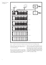
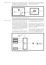
The alarm annunciator unit comprises a serial
communication port over which the unit can
be connected to a local reporting and data com-
munication system using the SPA bus protocol.
The physical connection for the serial interface
is located on the screw terminals on the back of
the unit using terminals 121,122,123,133, and
134 (se figure 19) The serial interface is accord-
ing to the RS 485 standard.
Using electrical connection the transfer distance
is about 20 to 30 m depending on the interfer-
ence level of the installation. The maximum al-
lowed ground potential difference between the
units is
±
10V.
A fiber optical connection module, SPA-ZC 17
or SPA-ZC 21 is used to connect the unit to a
fiber optical bus. The transfer distance using
fiber optical media is approximately 30 m for
plastic fiber and 2 km for glass fiber.
Note!
Because of the disturbant environment (like in
substations) where the units are operating it is
always recommended to use fiber optical com-
munication.
By using the LON/SPA gateway, SPA-ZC 100,
the alarm annunciator might also be connected
to the LON bus.
The SPA bus protocol is described in the docu-
ment SPA bus communication protocol V2.5,
34 SPACOM 2 EN1 and the LON Talk proto-
col is described in the document LON bus -
LON Works network in protection and control
systems; 1MRS750035-MTD EN
The speed of the serial communication is nor-
mally 9600 bits/s
Through the serial communication the follow-
ing information is read from the unit:
- the event registers including the time markings
- the state of the channels and of the system
- the programmed parameter values
- pulse counter values
The following data can be written to the unit:
- time synchronization
- audible device reset
- alarm channels acknowledge and reset
- control of an alarm channel
- control of output relays
- control of the interlocking channels
- setting values
- testing of the unit
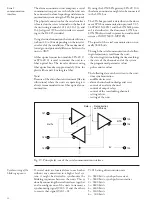
Fig. 19. Principle lay-out of the serial communication interface.
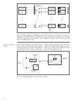
Synchronizing of the
blinking sequence
If several units are located close to each other
without any connection to a higher level sys-
tem, it might be desired to synchronize the
blinking sequences between the units. This is
done by connecting the serial interfaces together
and to configure one of the units to transmit a
synchronizing signal (V201=1) and the others
to receive that signal (V201 = 0).
V201 Setting of transmission rate
0 = 9600 bits/s, synch pulse receiver
1 = 9600 bits/s, synch pulse transmitter
2 = 9600 bits/s
3 = 4800 bits/s
4 = 2400 bits/s
5 = 1200 bits/s
6 = 300 bits/s
8V
RTS
Data
Data direction
on SPA-bus
Rx/Tx
121
122
123
133
134
135