L2234
Emax
79/158
Model
Scale
Page No.
Doc. No.
Apparatus
1SDH000460R0002
L2778
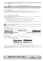
Watchdog for proper connection of the trip coil (TC). If it is enabled, any anomalies are indicated by a special alarm message and the "alarm"
LED coming on. If the PR120/D-M module is installed, this activates the coil opening command (YO), thus opening the CB.
Watchdog for protection of Hw Trip. If it is enabled, in the event of the sensors being disconnected or a Rating Plug error, a CB opening command
is given by the TC being enabled.
14.2.9 Description of the protection functions
14.2.9.1
Protection “L”
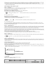
The "L" is the only protection that cannot be disabled because it is for self-protection against overloading of the relay itself. The types of trip curves
settable are divided into two groups according to the standard they refer to.
Standard trip curve according to IEC 60947-2
Only one type of curve is settable (t=k/I
2
) as defined by the IEC standard 60947-2.
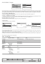
The protection trip time - inverse time - is given by the expression:
where l
f
<
12ln
, 1s where
l
f
>
12
ln
where
I
f
is the fault current and
I
1
the protection threshold.
NB: Time expressed in seconds.
Standard trip curve according to IEC 60255-3
There are 3 types of curves settable, defined by the IEC standard 60255-3 as A, B and C.
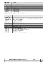
The protection trip time - inverse time - is given by the expression:
NB: Time expressed in seconds.
a
and
k
are two parameters, suggested by the standard, which vary the type of slope selected (e.g. for type B slope
a
=1 and
k
=13.5);
b
is a parameter introduced by SACE to increase the number of curves with the same slope. This parameter is automatically calculated by setting
the parameter t1 (required trip time at 3xI1).
4.2.9.1.1
Thermal memory “L”
The thermal memory function can be enabled for cable protection. It is based on the“
τ
L” parameter defined as the trip time of the curve (t1) selected
at 1.25xI1. The release trip time is certainly 100% of the one selected, after an interval
τ
L has passed since the last overload or since the last trip.
Otherwise, the trip time will be reduced, depending on the overload which has occurred and on the time that has elapsed.
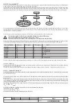
The PR123/P is fitted with two instruments to make up this thermal memory. The first is only effective when the release is powered (it also records
overloads that have not lasted long enough to trip the release), while the second works even when the release is not powered, reducing any trip
times in the case of an immediate reclosing and is enabled as soon as the CB is tripped.
It is the PR123/P release that automatically decides which of the two to use, according to the various situations.
N.B.: The thermal memory function can only be set if the type of curve selected is the standard one (t=k/I
2
) (see par. 14.2.9.1).
14.2.9.2
Protection “S”
This protection can be disabled; it can be of the fixed time (t=k) or inverse time (t=k/i
2
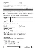
) type. In the latter case, the trip time is given by the expression:
14.2.9.2.1 Thermal memory “S”
The thermal memory function can be enabled for cable protection in the case where the curve with inverse time is selected. This is based on the
"tS" parameter defined as the trip time of the curve (t2) selected at 1.5xI2. The other characteristics are the same as those for thermal memory
"L" (see par. 14.2.9.1.1).
14.2.9.2.2 Start-up threshold “S”
The start-up function can be selected in the case where the curve with fixed time is selected.
The function can be disabled and it is a setting characteristic of the single protection units.
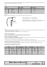
The start-up function enables the protection threshold (S, D, I and G) to be changed during a time interval lasting "ts", starting from "start-up". The
latter must be intended as follows:
- Passage of the RMS value of the maximum current over one single adjustable threshold (0.1…10In, by 0.1In steps). A new start-up is possible
after the current has dropped below this threshold.
where
( )
b
I
k
t
•
−
=
1
α
I
f
is the fault current and
I
1
the protection threshold specified by the user.
1
I
I
I
f
=
• Start-up time
The start-up time is common to all the protections involved.
Range: 0.1s ... 30s, with steps of 0.01s.
where
I
f
is the fault current and
I
2
the protection threshold.
( )
2
2
2
,
100
max
t
I
t
f
⎥
⎥
⎦
⎤
⎢
⎢
⎣
⎡
⋅
2
I
I
f
>
where
I
t h
Start Up Threshold I
2
Start Up
Programmed time
t
s
Threshold I
2

