L2234
Emax
47/158
Model
Scale
Page No.
Doc. No.
Apparatus
1SDH000460R0002
L2778
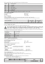
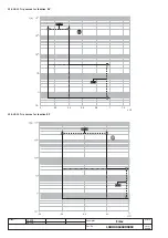
The PR122/P unit can provide two different types of earth fault protection as
an alternative:
Internal protection G
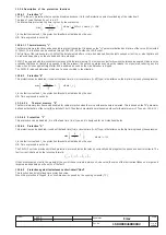
This is provided inside the relay by vectorially summing the phase and neutral currents. The fault current is defined by the following formula:
In the case when the circuit does not show any fault, the module of the sum of these currents is always nil; vice versa the value of the fault current
will take on an increasingly large value depending on the size of the fault. This operating mode is enabled by default.
N.B.: it can be used also with CS for an external neutral.
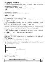
Protection G with external toroid "Source Ground Return"
Also called "Source Ground return", this can be carried out when there is the need to check operation of a machine (transformer, generator or
motor etc.) which has star-configured windings.
The protection is assured by physically positioning an external toroid on the cable connected from the star center of the machine to the earthing
connection point.
The induced current on the winding of the toroid is proportional to the fault current which, in this case, only transits in the above-mentioned toroid.
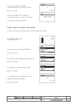
To work in this mode, "Ground protection" must be selected on the Circuit-breaker Settings menu.
The external toroid must be connected to the PR122/P by means of a corded shielded two-wire cable (see note A in par. 11.2.2)
with a length not exceeding 15m.
The shield must be earthed both on the circuit-breaker side and on the toroid side
.
It is indispensable for the star center to be connected openly to earth and for it not to be used as a neutral conductor too (as in the TNC system),
making a protection according to the TT system.
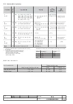
The minimum allowable threshold for the Gext protection is 0.1 x In (where In is the rated current
of the homopolar toroidal transformer; the In settings available are 100, 250, 400, 800A).
13.2.9.5.1
Start-up threshold “G”
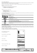
The start-up function can be selected in the case where the curve with fixed time is selected.
The function can be enabled and disabled on the protection "G" page.
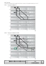
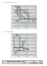
The function behaves in exactly the same way as the protection "S" (see par. 13.2.9.2.2).
13.2.9.5.2 Zone selectivity “G”
The zone selectivity function can be enabled providing the fixed time curve is selected, and function is assured only if auxiliary voltage is provided.
Zone selectivity "G" can be active at the same time as zone selectivity "S".
The behavior and wiring of the function are identical to those indicated for zone selectivity "S" (see par. 13.2.9.2.3).
13.2.9.6
Protection against phase unbalance “U”
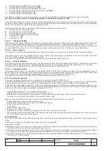
The protection with fixed time, which can be excluded, trips in the case when, for a time greater than or the same as the time
t6
set, an unbalance
is determined between two or more phases higher than the set threshold
I6
. Range: 2 … 90% by 1% steps.
The percentage of unbalance is therefore calculated %
Unb
=
100
max
min
max
⋅
−
=
I
I
I
where I
max
is the maximum and I
min
is the minimum phase current.
It is possible to disable the trip control of the protection ("Enable Trip: Off").
In that case, for the whole duration of the unbalance the CB will not be opened, but only the condition will be signaled by
means of the "warning" LED lit up and a warning message.
When the value of the phase current is above 6xIn, the function "U" excludes itself because, in this case, the other protections
intervene because the fault is considered as a phase fault.
The protection is not enabled for maximum phase current values lower than 0.3xIn.
13.2.9.7 Protection against overtemperature inside the relay “OT”
There is a sensor inside the PR122/P unit that monitors the temperature of the unit.
This enables the signalling of any abnormal temperature conditions, which could cause temporary or continuous malfunctions of the unit's electronic
components.
This protection has two states of operation:
State of
“WARNING TEMPERATURE”
with
–25 °C < temp. < -20 °C
or
70 °C < temp. < 85 °C
: the display is turned off
and the "WARNING" LED flashes at 0.5Hz
State of
“ALARM TEMPERATURE”
with
temp. < –25 °C
or
temp. > 85 °C
: the display is turned off,
the "WARNING" and “ALARM” Leds flash at 2Hz and the Trip is activated (if enabled by means of the "Over Temper. Trip = On" parameter)
N.B.:
In the event of Warning and Alarm, the display is turned off, to preserve its functionality.
The monitored temperature is not visible on the display.
The protection is always active, both with auxiliary supply and in self-supply.
Disabling the Trip control of the protection means that the PR122/P unit could work, with the circuit-breaker closed, in a range
of temperatures where correct operation of the electronics is not guaranteed.

