L2234
Emax
32/158
Model
Scale
Page No.
Doc. No.
Apparatus
1SDH000460R0002
L2778
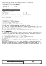
The presence of the auxiliary power supply enables the relay unit to be used even with the circuit-breaker open.
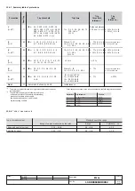
The characteristics of the power pack are given in the table below.
Characteristics
Version PR121/P
Auxiliary voltage
(galvanically separated)
24V DC ±20%
Maximum ripple
5%
Inrush current @ 24V
~10A for 5 ms
Rated power @ 24V
~2W
12.2.3 Environmental characteristics
Operating temperature
-25°C ... +70°C
Storage temperature
-40°C ... +90°C
Relative humidity
0% ... 98% with condensation
Degree of protection (with PR121/P installed in the circuit-breaker)
IP 30
12.2.4 Communication bus
Local bus on rear connector; RS485 physical interface, Modbus protocol.
Test bus on front test connector.
12.2.5 Protection functions
The PR121/P unit provides 5 independent protection functions, i.e.:
1. protection against overload with inverse time “
L
”;
2. protection against short-circuit with adjustable delay “
S
”;
3. protection against instantaneous short-circuit “
I
”;
4. protection against earth fault with adjustable delay “
G
”;
5. protection against instantaneous short-circuit at high currents “
Iinst
”.
The PR121/P unit allows the neutral pole's current signal to be processed using different relationships with the value of the phases.
N.B.: Beyond 15.5xIn of current on the Ne, the protection is considered as being set to 100%.
12.2.5.3
Watchdog
The PR121/P unit provides some watchdog functions to guarantee the proper management of relay malfunctions. These functions are as follows:
Rating PLUG validity.
Watchdog for proper current sensor connection (CS). Any anomalies are indicated by the LED coming on, as explained in par. 12.7.1.
Watchdog for proper opening solenoid connection (TC). Any anomalies are indicated by the LED coming on, as explained in par. 12.7.1.
Watchdog for protection against Hw Trip. If the sensors are disconnected or there is a Rating Plug error, when activated, a CB opening command
is issued due to the TC being activated. This function can be activated through a PR010/T test unit.
12.2.5.2
Measuring Function
A current measuring function (ammeter) is available on all versions of the PR121/P unit.
This function can be accessed through a PR10/T test unit only via a test bus and through HMI030 via a local bus.
With auxiliary voltage, the protection records a historical of the maximum current read.
12.2.5.1
Calculating the RMS
All the protection functions do their respective processing on the basis of the real rms value of the currents (the protection G is disabled for current
values greater than 8In [where I
4
>0,8In], greater than 6In [where 0.5In
≤
I4<0.8In] and greater than 4In [where I
4
<0,5In].
If the waveform has a deformation beyond the declared limit (6.3@2In), the tolerance for the calculation of the true rms value will increase.
A timing indication ("alarm" LED) is provided on the front of the unit, which is enabled during an alarm for each protection; it is disabled when the
alarm condition ceases or when the protection has been tripped.
The unit also has a "backup protection" function. If the circuit-breaker does not open immediately the first time the Trip Coil is hit (partial TC failure),
TRIP commands are sent repeatedly until the circuit-breaker opens.
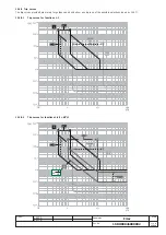
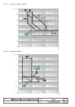
For the inverse-time protections, the relationship between trip time and overcurrent is given by the formula: t=k/I
2
.
For the fixed-time protections with an adjustable delay, the relationship adopted is as follows: t=k.

