Page 24
REM 543 Protection,
Monitoring and Control
Technical Reference Manual
Part 1, General
ABB Network Partner
thermore, the machine terminal has two internal analogue channels, channels 11 and 12,
which form the calculated neutral current and residual voltage from phase currents and
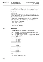
voltages. The machine terminals have the following analogue channels.
Measuring units
Ch No.
Current
Transformer
(CT)
Voltage
Transformer
(VT)
Rogovski coil/-
sensor (RS)
Voltage divider
(VD)
Signal type
(selectable
alternatives)
1
RS type 1, 2, 3
VD type 1, 2, 3
Not in use, I
L1
,
I
L2
, I
L3
, I
L1b,
I
L2b,
I
L3b,
U
1
,
U
2
, U
3
, U
1b
,
U
1c
2
Current
Transformer
CT1
(I
n
= 1 A/5 A)
RS type 1, 2, 3
VD type 1, 2, 3
Not in use, I
L1
,
I
L2
, I
L3
, I
L1b,
I
L2b,
I
L3b,
I
0
,
I
0b
, U
1
, U
2
, U
3
,
U
1b
, U
1c
3
Current
Transformer
CT2
(I
n
= 1 A/5 A)
RS type 1, 2, 3
VD type 1, 2, 3
Not in use, I
L1
,
I
L2
, I
L3
, I
L1b,
I
L2b,
I
L3b,
I
0
,
I
0b
, U
1
, U
2
, U
3
,
U
1b
, U
1c
4
Current
Transformer
CT3
(I
n
= 1 A/5 A)
RS type 1, 2, 3
VD type 1, 2, 3
Not in use, I
L1
,
I
L2
, I
L3
, I
L1b,
I
L2b,
I
L3b,
I
0
,
I
0b
, U
1
, U
2
, U
3
,
U
1b
, U
1c
5
Current
Transformer
CT4
(I
n
= 1 A/5 A)
Voltage
Transformer
VT1
(U
n
=100V/
110V/115V/
120V)
Not in use, I
L1
,
I
L2
, I
L3
, I
L1b,
I
L2b,
I
L3b,
I
0,
I
0b
, U
0
, U
12
,
U
23
, U
31
,
U
12b
, U
12c
,
U
1
, U
2
, U
3
,
U
1b
, U
1c
6
Current
Transformer
CT5
(I
n
= 1 A/5 A)
Voltage
Transformer
VT2
(U
n
=100V/
110V/115V/
120V)
Not in use, I
L1
,
I
L2
, I
L3
, I
L1b,
I
L2b,
I
L3b,
I
0,
I
0b
, U
0
, U
12
,
U
23
, U
31
,
U
12b
, U
12c
,
U
1
, U
2
, U
3
,
U
1b
, U
1c


