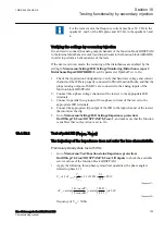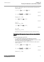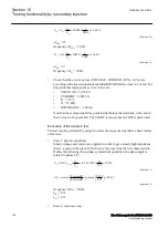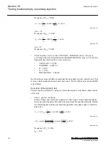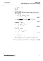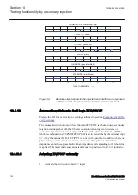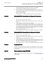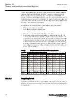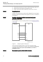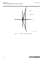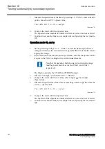
During normal operating conditions, the
BC
input is de-energized.
2.
Set
AutoInitMode
to
DLD disabled
and
Mode
to
Impedance
.
3.
Apply a three-phase fault condition corresponding to a fault at approximately
45% of the line or with impedance at 50% of the used zone setting and current
greater than 30% of
IBase
.
The
ZACC
input is activated.
4.
Check that the
TRIP
output, external signals and indication are obtained.
10.4.13.2
Initiating ZCVPSOF automatically and setting mode to impedance
1.
Deactivate the switch onto fault
BC
input.
2.
Set the current and voltage inputs to lower than
IPh<
and
UPh<
for at least one
second.
3.
Set
AutoInitMode
to
Voltage
and
Mode
to
Impedance
.
4.
Apply a three-phase fault condition corresponding to a fault at approximately
45% of the line or with impedance at 50% of the used zone setting and current
greater than 30% of
IBase
.Apply a two-phase fault condition corresponding to
a fault at approximately 45% of the line or with impedance at 50% of the used
zone setting and current greater than 30% of
IBase
.
The
ZACC
input is activated.
5.
Check that the correct
TRIP
output, external signals and indication are obtained.
10.4.13.3
Initiating ZCVPSOF automatically and setting mode to UILevel
1.
Deactivate the switch onto fault
BC
input.
2.
Set the current and voltage inputs to lower than
IPh<
and
UPh<
for at least one
second.
3.
Set
AutoInitMode
to
Voltage
and
Mode
to
UILevel
.
4.
Apply the three-phase currents in such a way that the magnitudes are greater than
IPh<
and the three-phase voltages in such a way that the magnitudes and lower
than
UPh<
at least for the duration of the
tDuration
setting.
5.
Check that the correct
TRIP
output, external signals and indication are obtained.
10.4.13.4
Completing the test
Continue to test another function or end the test by changing the
TestMode
setting to
Off
. Restore connections and settings to their original values, if they were changed for
testing purposes.
10.4.14
Phase preference logic PPLPHIZ
Prepare the IED for verification of settings outlined in section
.
1MRK 506 355-UEN A
Section 10
Testing functionality by secondary injection
Line distance protection REL670 2.1 IEC
143
Commissioning manual
Содержание Relion 670 Series REL670
Страница 1: ...Relion 670 series Line distance protection REL670 2 1 IEC Commissioning manual ...
Страница 2: ......
Страница 30: ...24 ...
Страница 34: ...28 ...
Страница 64: ...58 ...
Страница 68: ...62 ...
Страница 90: ...84 ...
Страница 254: ...248 ...
Страница 260: ...254 ...
Страница 269: ...263 ...

