48
Configuring the fibre optical modem
&KDSWHU
&RQILJXULQJWKHGLJLWDO
FRPPXQLFDWLRQPRGXOHV
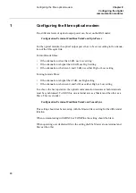
&RQILJXULQJWKHILEUHRSWLFDOPRGHP
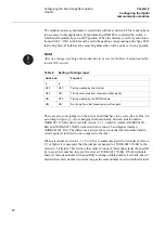
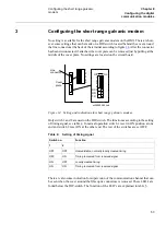
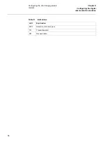
Two different levels of optical output power can be set on the HMI under:
&RQILJXUDWLRQ7HUPLQDO&RP5HP7HUP&RP2SWR3RZHU
For the optical module, the optical output power has to be set according to the attenua-
tion of the fibre optic link.
For multimode fibres:
•
If the attenuation is less than 6 dB, use Low setting
•
If the attenuation is higher than 10 dB, use High setting
•
If the attenuation is between 6 and 10 dB, use either High or Low setting
For single-mode fibres:
•
If the attenuation is higher than 5 dB, use High setting
•
If the attenuation is between 0 and 5 dB, use either High or Low setting
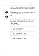
To achieve the best operation, the optical communication modules at both terminals
must be synchronised. To fulfil this, one terminal acts as a Master and the other as a
Slave. This is set under:
&RQILJXUDWLRQ7HUPLQDO&RP5HP7HUP&RP&RPP6\QF
This setting should not be mixed up with the Master-Slave setting for the differential
function.
When communicating with FOX20 or FOX6Plus, the setting should be Slave.
When operating over dedicated fibres the setting shall be Master at one terminal and
Slave at the other.
Содержание REL 531
Страница 16: ...10 Note signs KDSWHU 6DIHW LQIRUPDWLRQ ...
Страница 44: ...38 Checking the binary I O circuits KDSWHU KHFNLQJ WKH H WHUQDO FLUFXLWU ...
Страница 52: ...46 Checking the self supervision signals KDSWHU QHUJLVLQJ WKH WHUPLQDO ...
Страница 132: ...126 Two step time delayed phase overcurrent protection TOC2 KDSWHU 9HULI LQJ VHWWLQJV E VHFRQGDU LQMHFWLRQ ...
Страница 136: ...130 Testing the interaction of the distance protection KDSWHU 9HULI LQJ WKH LQWHUQDO FRQILJXUDWLRQ ...
Страница 140: ...134 Testing the interaction of the distance protection KDSWHU 7HVWLQJ WKH SURWHFWLRQ V VWHP ...

