


I.L. 40-386.3
(10/94)
5-13
“Dir Type”
=
“Zero sequence” (Directional overcurrent polarization choice setting)
“GB Type”
=
“Disabled” (Overcurrent ground backup curve family setting)
Test Using Blocking System
Apply an AG fault as described in Step 6 above. The REL 302 should
not
trip.
Apply rated dc voltage to terminals TB4-9(+) and TB4-10(-). Again apply an AG fault
as described in Step 6 above. When the relay trips, remove the fault current. PILOT
and AG LED’s will light. The LCD display will switch to the L-FLT mode and fault dis-
tance will be displayed. Using the RAISE and LOWER push-buttons the complete fault
record can be reviewed.
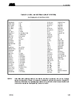
See Table 4-3 for a description of the displayed fault data quan-
tities.
The significant quantities to review are:
Fault Type
— “FLT Type” “AG”
Targets
— “Pilot G” “YES”
Fault Voltages (VA, VB, VC, 3V0) and Currents (IA, IB, IC, 3I0)
Pressing the front panel RESET push-button will cause the LCD display to switch to
the METER display and the LEDs will stop flashing.
STEP 13
Receiver Inputs 1 and 2
Apply rated dc voltage to terminals TB4-9(+) and TB4-10(-) for tests a and b below.
a.
Blocking System Test
Apply an AG fault as
described in Step 6
. The REL 302
should
trip. When the relay
trips, remove the fault current. PILOT and AG LEDs will light. The LCD display will
switch to the L-FLT mode and fault distance will be displayed. Using the RAISE
and LOWER push-buttons the complete fault record can be reviewed.
See Table 4-
2 for a description of the displayed fault data quantities.
The significant quantities to review are:
Fault Type
— “FLT Type” “AG”
Targets
— “Pilot G” “YES”
Fault Voltages (VA, VB, VC, 3V0) and Currents (IA, IB, IC, 3I0)
Pressing the front panel RESET push-button will cause the LCD display to switch
to the METER display and the LEDs will stop flashing.
Applying rated dc voltage to terminals TB4-11(+) and TB4-12(-) simulates the re-
ceipt of a pilot blocking signal. Again apply an AG fault as described in Step 6. The
REL 302 should
not
trip. Remove voltage from terminals TB4-11 and TB4-12.
Receipt of the pilot signal can also be simulated from the front panel. Using the
procedure outlined in Step 5, press the SELECT push-button until the “TEST”
mode is selected. Displayed is the result of the self-test routine which should show
a normal status, “Status” “0”.
Содержание REL 301
Страница 1: ......
Страница 8: ......
Страница 17: ...I L 40 386 3 1 10 10 94 2682F39 Sheet 1 of 2 Sub 2 Figure 1 2 REL 301 302 Layout Vertical...
Страница 18: ...I L 40 386 3 10 94 1 11 2682F39 Sheet 2 of 2 Sub 2 Figure 1 3 REL 301 302 Layout Horizontal...
Страница 19: ......
Страница 20: ......
Страница 44: ......
Страница 46: ......
Страница 48: ......
Страница 49: ......
Страница 51: ......
Страница 53: ......
Страница 54: ......
Страница 55: ......
Страница 56: ......
Страница 57: ......
Страница 60: ......
Страница 61: ...I L 40 386 3 2 40 10 94 1501B84 Sub 6 Figure 2 31 Reversible Zone3 Phase and Ground Reverse Block Logic...
Страница 62: ...I L 40 386 3 10 94 2 41 Figure 2 32 CO 2 Curve Characteristics 619596 Sub 2...
Страница 63: ...I L 40 386 3 2 42 10 94 Figure 2 33 CO 5 Curve Characteristic 619597 Sub 2...
Страница 64: ...I L 40 386 3 10 94 2 43 Figure 2 34 CO 6 Curve Characteristic 619598 Sub 2...
Страница 65: ...I L 40 386 3 2 44 10 94 Figure 2 35 CO 7 Curve Characteristic 619599 Sub 2...
Страница 66: ...I L 40 386 3 10 94 2 45 Figure 2 36 CO 8 Curve Characteristic 619600 Sub 2...
Страница 67: ...I L 40 386 3 2 46 10 94 Figure 2 37 CO 9 Curve Characteristic 619601 Sub 2...
Страница 68: ...I L 40 386 3 10 94 2 47 Figure 2 38 CO 11 Curve Characteristic 619602 Sub 2...
Страница 126: ...I L 40 386 3 10 94 5 19 Figure 5 3 Microprocessor Module JP6 JP5 JP3 JP4 Clock Battery 1613C55 Sheet 3 of 3 Sub 6...