I.L. 40-386.3
(10/94)
5-7
b.
The “TEST” display mode also provides access for testing for REL 301/302 output relay
contacts. All output relays will be tested using the procedure described in Step 12. In asso-
ciation with the contact test, receiver 1 and/or 2 units can be simulated for verification of
REL 302 pilot logic. These input simulations will be used later in
Section 5.2 Pilot Accep-
tance Tests for REL 302.
As previously stated, when REL 301 or REL 302 are energized the system performs a
complete self-test/startup/initialization routine. Upon successful completion of the
startup routine the system firmware enters what is referred to as the background
mode. In the background mode all “non-fault analysis” functions are performed. In the
background mode, current and voltage sampling is done continuously (2 millisecond
resolution) as well as the calculation of current and voltage phasors. Also, when the
system is in background mode MMI functions and (continuous) self-checking are per-
formed.
See Figure 1-6 for software flowchart reference.
Tripping decisions are made in the fault mode. Both the REL 301 and REL 302 utilize
a unique disturbance detector that is used to switch from background mode to fault
mode processing. In fault mode only processing related to fault calculation trip logic
analysis are done. All background mode functions not related to tripping are stopped.
The operate criteria for the disturbance detector (Fault Detector) are:
Phase current (
∆
IA,
∆
IB, or
∆
IC) > 1.0A peak and 12.5% change
Ground current (
∆
I0)>0.5 A peak
Phase voltage (
∆
VA,
∆
VB, or
∆
VC) >7V and 12.5% change with a current change of
∆
I>0.5 A
When one of the above is met, REL 301 or REL 302 will switch to fault mode process-
ing.
In order to perform all tests, voltages will be applied first then the designated value of
current has to be
suddenly
applied. If REL 301 or REL 302 does not trip, adjust the
current to a higher value, and then suddenly reapply current. Unlike conventional
electromechanical relays, slowly ramping up the current will not cause
Zone
1 tripping.
The current required to trip is shown for each test.
5.1.4
Zone
1 Impedance Accuracy Check
STEP 6
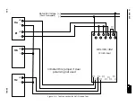
With the system under test connected
as shown in Figure 5-4
and with the settings
from
Table 5-1 (5-2 for REL 302)
applied to the system, adjust the voltages as follows:
V
A
= 30 ang 0
°
V
B
= 70 ang -120
°
V
C
= 70 ang 120
°
Apply current to the A phase current input as shown. The current required to trip is
4.00 amps
±
5% at an angle of 75
°
lagging the fault voltage. This is the “maximum
torque angle” test.
Содержание REL 301
Страница 1: ......
Страница 8: ......
Страница 17: ...I L 40 386 3 1 10 10 94 2682F39 Sheet 1 of 2 Sub 2 Figure 1 2 REL 301 302 Layout Vertical...
Страница 18: ...I L 40 386 3 10 94 1 11 2682F39 Sheet 2 of 2 Sub 2 Figure 1 3 REL 301 302 Layout Horizontal...
Страница 19: ......
Страница 20: ......
Страница 44: ......
Страница 46: ......
Страница 48: ......
Страница 49: ......
Страница 51: ......
Страница 53: ......
Страница 54: ......
Страница 55: ......
Страница 56: ......
Страница 57: ......
Страница 60: ......
Страница 61: ...I L 40 386 3 2 40 10 94 1501B84 Sub 6 Figure 2 31 Reversible Zone3 Phase and Ground Reverse Block Logic...
Страница 62: ...I L 40 386 3 10 94 2 41 Figure 2 32 CO 2 Curve Characteristics 619596 Sub 2...
Страница 63: ...I L 40 386 3 2 42 10 94 Figure 2 33 CO 5 Curve Characteristic 619597 Sub 2...
Страница 64: ...I L 40 386 3 10 94 2 43 Figure 2 34 CO 6 Curve Characteristic 619598 Sub 2...
Страница 65: ...I L 40 386 3 2 44 10 94 Figure 2 35 CO 7 Curve Characteristic 619599 Sub 2...
Страница 66: ...I L 40 386 3 10 94 2 45 Figure 2 36 CO 8 Curve Characteristic 619600 Sub 2...
Страница 67: ...I L 40 386 3 2 46 10 94 Figure 2 37 CO 9 Curve Characteristic 619601 Sub 2...
Страница 68: ...I L 40 386 3 10 94 2 47 Figure 2 38 CO 11 Curve Characteristic 619602 Sub 2...
Страница 126: ...I L 40 386 3 10 94 5 19 Figure 5 3 Microprocessor Module JP6 JP5 JP3 JP4 Clock Battery 1613C55 Sheet 3 of 3 Sub 6...


