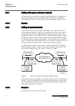
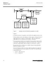
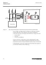
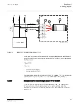

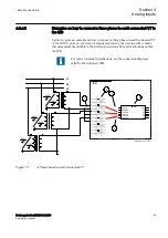
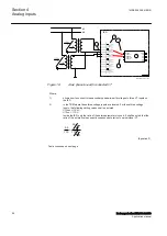
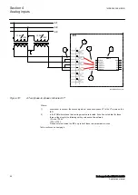
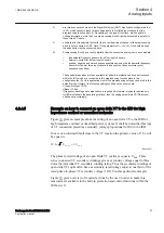


For correct terminal designations, see the connection diagrams
valid for the delivered IED.
Protected Object
L1
L2
L3
IED
IN
P
INS
INS
2
IEC11000029-4-en.vsdx
4
3
C
T
1000
/1
a)
b)
(+)
(+)
(-)
(-)
(+)
(-)
1
SMAI2
BLOCK
REVROT
^GRP2L1
^GRP2L2
^GRP2L3
^GRP2N
AI3P
AI1
AI2
AI3
AI4
AI N
IEC11000029 V4 EN-US
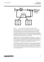
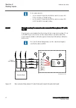
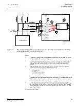
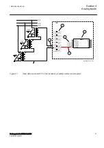
Figure 15:
Connections for single-phase CT input
Where:
1)
shows how to connect single-phase CT input in the IED.
2)
is TRM where these current inputs are located. It shall be noted that for all these
current inputs the following setting values shall be entered.
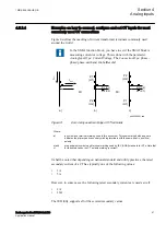
For connection (a) shown in Fgure
:
CTprim= 1000 A
CTsec= 1A
CTStarPoint=ToObject
For connection (b) shown in Figure
CTprim= 1000 A
CTsec= 1A
CTStarPoint=FromObject
3)
shows the connection made in SMT tool, which connect this CT input to the fourth input
channel of the preprocessing function block 4).
4)
is a Preprocessing block that has the task to digitally filter the connected analog inputs
and calculate values. The calculated values are then available for all built-in protection
and control functions within the IED, which are connected to this preprocessing
function block.
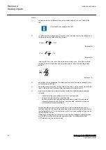
If frequency tracking and compensation is required (this feature is typically required
only for IEDs installed in the power plants) then the setting parameters
DFTReference
shall be set accordingly.
Section 4
1MRK 505 388-UEN B
Analog inputs
50
Busbar protection REB650 2.2 IEC
Application manual
Содержание REB650
Страница 1: ...RELION 650 SERIES Busbar protection REB650 Version 2 2 Application manual...
Страница 2: ......
Страница 18: ...12...
Страница 28: ...22...
Страница 38: ...32...
Страница 78: ...72...
Страница 96: ...90...
Страница 136: ...130...
Страница 150: ...144...
Страница 156: ...150...
Страница 232: ...226...
Страница 278: ...272...
Страница 298: ...292...
Страница 310: ...304...
Страница 320: ...314...
Страница 321: ...315...


