


•
In case a total interruption (low current) of the protected transformer all
cooling possibilities will be inactive. This can result in a changed value of the
time constant.
•
If other components (motors) are included in the thermal protection, there is a
risk of overheating of that equipment in case of very high current. The thermal
time constant is often smaller for a motor than for the transformer.
ITrip:
The steady state current that the transformer can withstand. The setting is
given in % of
IBase1
or
IBase2
.
Alarm1
: Heat content level for activation of the signal ALARM1. ALARM1 is set
in % of the trip heat content level.
Alarm2
: Heat content level for activation of the output signal ALARM2. ALARM2
is set in % of the trip heat content level.
ResLo
: Lockout release level of heat content to release the lockout signal. When
the thermal overload protection trips a lock-out signal is activated. This signal is
intended to block switching on of the protected circuit transformer as long as the
transformer temperature is high. The signal is released when the estimated heat
content is below the set value. This temperature value should be chosen below the
alarm temperature.
ResLo
is set in % of the trip heat content level.
ThetaInit
: Heat content before activation of the function. This setting can be set a
little below the alarm level. If the transformer is loaded before the activation of the
protection function, its temperature can be higher than the ambient temperature.
The start point given in the setting will prevent risk of no trip at overtemperature
during the first moments after activation.
ThetaInit:
is set in % of the trip heat
content level.
Warning
: If the calculated time to trip factor is below the setting
Warning
a
warning signal is activated. The setting is given in minutes.
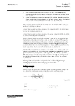
7.4.3.1
Setting example
GUID-37AB7D3E-9380-49A4-A47D-067E3E5DC914 v1
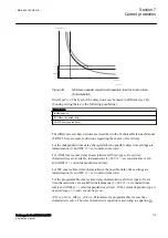
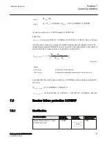
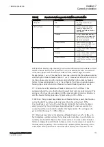
Calculation of the operate time with the available current is performed only if the
calculated final temperature is greater than the operate level temperature.
ln
final
operate
operate
final
n
t
t
æ
ö
Q
- Q
= - × ç
÷
ç
÷
Q
- Q
è
ø
EQUATION1176 V1 EN-US
(Equation 28)
where:
t
operate
is the time to operate
t
is the time constant
Table continues on next page
1MRK 505 388-UEN B
Section 7
Current protection
Busbar protection REB650 2.2 IEC
121
Application manual
Содержание REB650
Страница 1: ...RELION 650 SERIES Busbar protection REB650 Version 2 2 Application manual...
Страница 2: ......
Страница 18: ...12...
Страница 28: ...22...
Страница 38: ...32...
Страница 78: ...72...
Страница 96: ...90...
Страница 136: ...130...
Страница 150: ...144...
Страница 156: ...150...
Страница 232: ...226...
Страница 278: ...272...
Страница 298: ...292...
Страница 310: ...304...
Страница 320: ...314...
Страница 321: ...315...


