


Operation Manual / Power2 650-M / Low-pressure stage
Figures
© Copyright 2022 ABB. All rights reserved.
HZTL4065_EN
Revision E
March 2022
Figures
Fig. 1: Power2 with bellows layout and function....... 7
Fig. 3: Function of the low-pressure stage ............... 9
nhibitor (VCI)................... 12
Fig. 5: Package with hygrometer................................ 13
Fig. 6: Location of Power2 LP warning plates ......... 18
Fig. 7: Rating plate ........................................................ 19
Fig. 8: Location of Power2 LP rating plate .............. 20
Fig. 9: Attachment of loads on the crane hook ....... 21
Fig. 10: Attachment angle............................................ 21
Fig. 11: Suspension of complete low-pressure stage..
31
Fig. 12: Suspension of complete low-pressure stage .
32
Fig. 13: Functional principle........................................ 40
Fig. 14: Dimension X...................................................... 41
Fig. 15: Removing the speed measurement system....
42
Fig. 16: Setting dimension X....................................... 42
Fig. 17: Control dimension S....................................... 43
Fig. 18: Cleaning the filter silencer............................ 54
Fig. 19: Cleaning the filter silencer (2) ...................... 56
Fig. 20: Cleaning the filter silencer ............................ 57
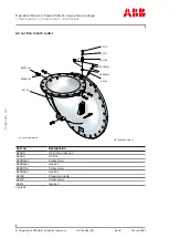
Fig. 21: Overview of assemblies................................. 68
Fig. 24: Measuring axial clearance A .......................... 71
Fig. 25: Removing wall insert 1.................................... 72
Fig. 26: Removing wall insert 2 ................................... 73
Fig. 27: Removing wall insert 3.................................... 73
Fig. 28: Removing the compressor casing 1 ........... 74
Fig. 29: Removing the compressor casing 2 ........... 74
Fig. 30: Moving out cartridge group 1....................... 75
Fig. 31: Moving out cartridge group 2........................ 76
Fig. 32: Putting down cartridge group onto cover . 76
Fig. 33: Removing turbine diffuser and nozzle ring 1 ..
77
Fig. 34: Removing turbine diffuser and nozzle ring 2 ..
77
Fig. 35: Removing turbine diffuser and nozzle ring 3 ..
78
Fig. 36: Removing turbine diffuser and nozzle ring 4..
78
Fig. 39: Installing O-rings ............................................. 81
Fig. 40: Installing the cartridge group 1.................... 81
Fig. 41: Inserting the cartridge group........................ 82
Fig. 42: Measuring control dimension X.................... 83
Fig. 43: Installing the compressor casing................. 84
Fig. 44: Installing the wall insert 1 .............................. 85
Fig. 45: Installing the wall insert 2.............................. 86
Fig. 46: Measuring axial clearance A .......................... 87
Fig. 47: Installing the air suction branch................... 88
Fig. 49: Overview of tightening torques ................... 90
Fig. 50: Cover plate / gasket, sleeves and screws .. 92
Fig. 51: Fitting the cover plate .................................... 93
Fig. 52: Installing the casing ........................................ 93
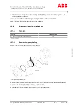
Fig. 53: Removing gas piping ..................................... 113
Fig. 54: Installing gas piping ...................................... 114
Page
117
/
119
Page
117
/
119