


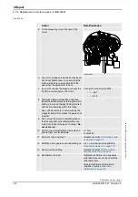

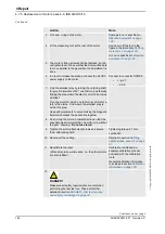

4 Repair
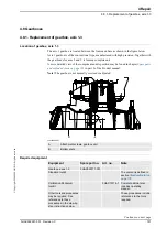
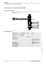
4.7.4. Replacement of motors, axes 4-6, IRB 2400L
3HAC022031-001 Revision: C
142
©
Co
py
rig
h
t 200
4-
200
8 ABB. All righ
ts reser
v
ed.
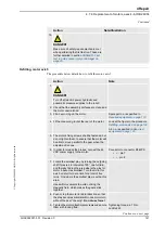
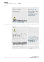
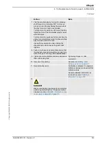
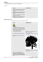
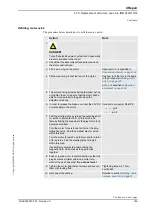
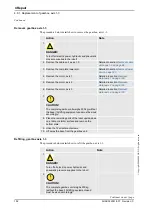
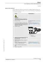
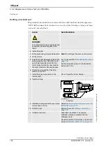
Refitting, motor axis 6
The procedure below details how to refit the motor, axis 6.
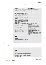
10. Reconnect the cabling.
11. Recalibrate the robot.
Calibration is detailed in a separate
calibration manual, enclosed with
the calibration tools.
General calibration information is
included in section
12.
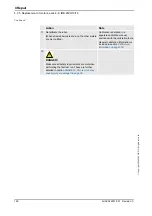
DANGER!
Make sure all safety requirements are met when
performing the first test run. These are further
detailed in section
cause injury or damage! on page 35
.
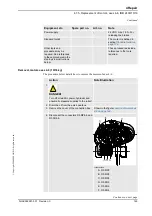
Action
Note
Action
Note
1.
DANGER!
Turn off all electric power, hydraulic and
pneumatic pressure supplies to the robot!
2. Check that the assembly surfaces are clean and
the motor unscratched
3. Fit an new
o-ring
on the motor.
Spare part no. is specified in
Required equipment on page 137
.
4. Fit the
measuring tool
at the rear of the motor.
Look at the figure in the procedure
Refitting, motor axis 4 on page 139
.
5. The motor’s fixing screws shall be fastened, but
do not tighten them, to esure that the motor will
be able to move parallel to the gear when the
adjustment is done
6. In order to release the brakes, connect the 24
VDC power supply to the motor.
Connect to connector R3.MP6:
•
+ : pin 7
•
- : pin 8
Continued
Continues on next page
Содержание IRB 2400/L
Страница 1: ...Product manual Articulated robot IRB 2400 L IRB 2400 10 IRB 2400 16 M2000 M2000A M2004 ...
Страница 2: ......
Страница 8: ...Table of Contents 6 3HAC022031 001 Revision C Copyright 2004 2008 ABB All rights reserved ...
Страница 16: ...Product documentation M2004 3HAC022031 001 Revision C 14 Copyright 2004 2008 ABB All rights reserved ...
Страница 191: ......
Страница 192: ......
Страница 193: ......
Страница 194: ......
Страница 195: ......
Страница 198: ......
Страница 199: ......
Страница 202: ......
Страница 203: ......
Страница 205: ......
Страница 210: ...8 Circuit diagram 8 1 Introduction 3HAC022031 001 Revision C 198 Copyright 2004 2008 ABB All rights reserved Continued ...
Страница 211: ...Manipulator Circuit Diagram 3HAC 6670 3 Rev 01 Product Manual IRB 2400 No of Sheets 13 Sheet no 101 LIST OF CONTENTS ...
Страница 214: ...Manipulator Circuit Diagram 3HAC 6670 3 Rev 01 Product Manual IRB 2400 No of Sheets 13 Sheet no 104 MOTOR AXIS 1 3 ...
Страница 226: ......