50
H I PE RG UA R D M V U PS
US ER M A N UA L
6.4.7 Ethernet communication interfaces
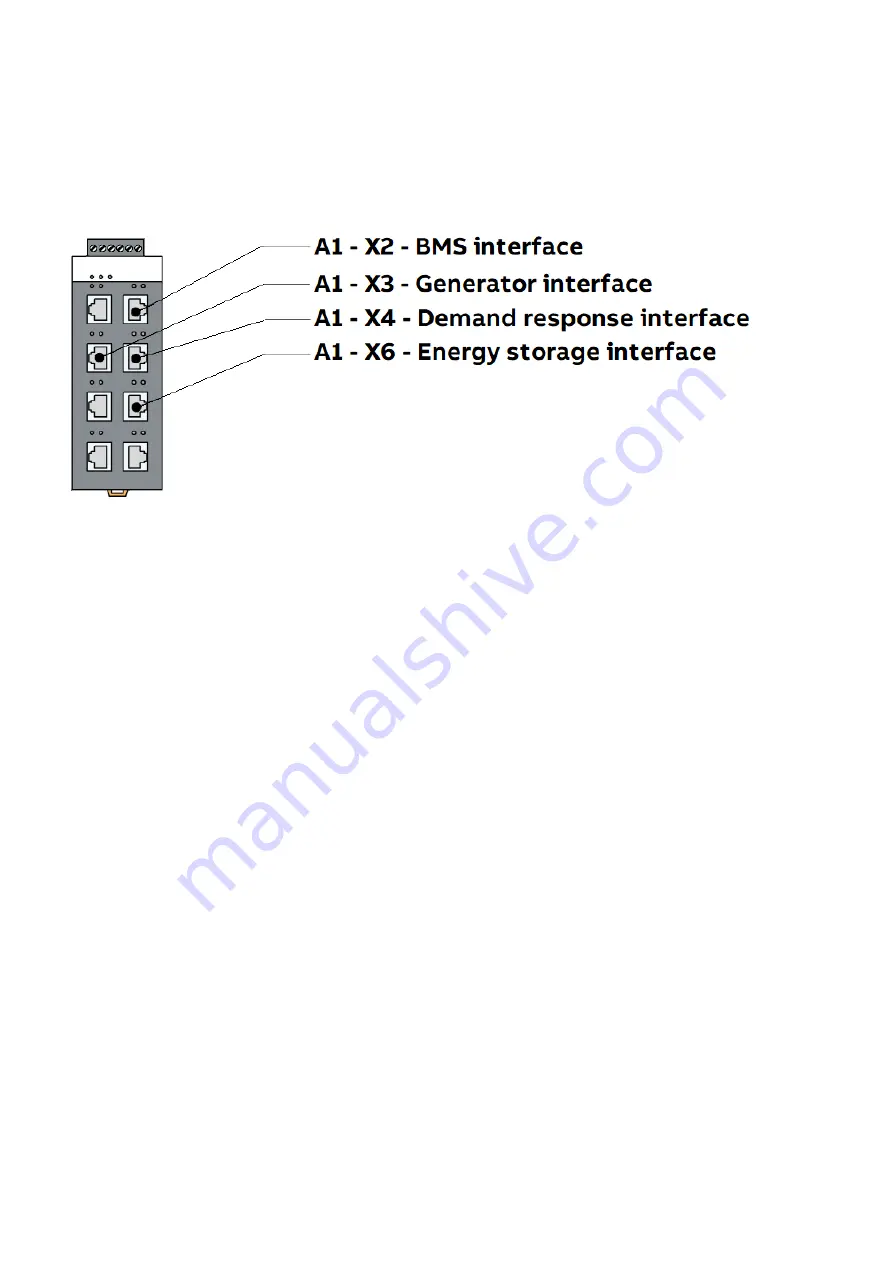
The Ethernet communications cables connected to the energy storage enclosure (Section 6.4.4), demand re-
sponse controller (6.4.5), and generator interface (6.4.6) are connected to the Ethernet switch A1, located in the
UPS APS enclosure. Figure 6.07 shows the location of these ports on the Ethernet switch.
—
Figure 6.07: Ether-
net switch ports.
6.4.8 Auxiliary AC power outputs
The HiPerGuard MV UPS has available two auxiliary 400Vac three-phase power supplies, for use as and when re-
quired.
The first power supply is internally fed, so is continuously available. This may be required, for example, by the En-
ergy Storage enclosure(s) for fan supply.
The second power supply is fed from the external three-phase site supply. Refer to Section 6.4.1.
Содержание HiPerGuard MV UPS
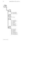
Страница 58: ...58 HIPERGUARD MV UPS USER MANUAL Figure 7 04 Pages map ...
Страница 84: ......


