33
3.3.4 DC Termination enclosure (DCT)
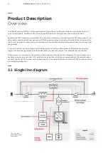
The DC Termination enclosure has the DC termination bars where the energy storage is connected to the MV UPS.
The enclosure is designed to accommodate up to fourteen terminal lugs (of each polarity) with M12 stud holes or
ten terminals with M16 holes.
—
Figure 3.28: DC Ter-
mination Enclosure
(DCT) - Bottom cable
entry version.
—
3.4 Cooling system
The LV enclosures and the MVM enclosure are equipped with fan units. The fan units suction cooling air to the HiP-
perGuard MV UPS major components with the objective of transfer the internally generated heat to the outside of
the enclosures.
The air enters the HiPerGuard MV UPS enclosures through the louver panels at the front and exits through the air
outlet at the top (except for the APS enclosure where the outlet is located on the front door).
The air intakes, including the louvers and filters, must be maintained unobstructed when the HiPerGuard MV UPS
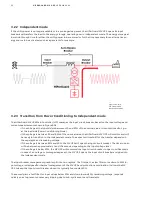
is operating. Figures 3.29 and 3.30 illustrate the air intake (blue arrows) and air out (red arrows). Please refer to
the Installation Manual for more information about the minimum recommended clearances for operation and
maintenance purposes.
—
Figure 3.29: Air
flow direction for
the front side.
Содержание HiPerGuard MV UPS
Страница 58: ...58 HIPERGUARD MV UPS USER MANUAL Figure 7 04 Pages map ...
Страница 84: ......


