24
H I PE RG UA R D M V U PS
US ER M A N UA L
—
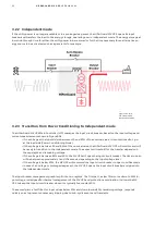
Figure 3.05: MV UPS
fed by an upstream
generator.
The MV UPS understands that the generator can handle the load when it increases the frequency back towards
nominal frequency. The MV UPS will support the load by clamping the frequency at 98% of the nominal until the
generator has completed picked up the load. The UPS does this all in a very smooth manner.
—
The process is the same for a single or several generators connected to
the MV UPS input busbar.
The minimum walk-in time is defined by the capacity of the generator (or generators) to support the load based
on the frequency error. There will be a tradeoff between how fast the generator governor responds to a frequency
error and the maximum frequency error the load can tolerate. Typically, 2% of the nominal frequency is chosen as
a suitable tradeoff for fast generator response while having minimal disturbance on the load.
Additionally, the maximum duration of the walk-in is limited by the capacity of the energy storage. The MV UPS
will share the load with the generator until the energy storage is depleted. If the generator cannot successfully
support the load during the walk-in procedure, and the energy storage is depleted, the MV UPS will transfer the
load to the auto-bypass breaker
A common configuration is to have multiple parallel generators connected in parallel to create a single common
generator bus, which when the grid is lost, the entire site switches over to the generator bus. The single bus may
feed both numerous different loads and MV UPS's.
3.2.5.1 Single common generator bus
—
Figure 3.06: Single
common generator bus
Содержание HiPerGuard MV UPS
Страница 58: ...58 HIPERGUARD MV UPS USER MANUAL Figure 7 04 Pages map ...
Страница 84: ......


