background image


D184B122U02

S4

35

Submenu/
Parameter

Submenu/

Parameter 

Submenu/
Parameter

Selections

Value Range

Comments

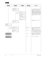
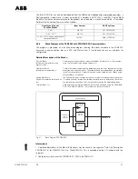
Iout at Alarm

Low Alarm
High Alarm

Behavior of the current output during an 
alarm condition. Low-Alarm is only available 
for current output selections 2-10 mA and 
4-20 mA. If error 0 (empty pipe) occurs, the 
current output is set to the value pro-
grammed for the parameter "Iout at empty 
pipe" in the submenu "Detector empty 
pipe". If error 3 (flowrate > 105 %) occurs, 
the current output is always set to the "High 
Alarm" value.

Low Alarm

Iout Low Alarm

numeric entry

Low-Alarm is only available for current out-
put selections 2-10 mA and 4-20 mA. Set 
the current output value during a Low Alarm 
condition. No selection is possible when the 
current output selection Iout High Alarm for 
Iout at Alarm was made and when the con-
verter version is standard and the current 
output range is 
0-20 mA
0-10 mA

3.60 mA

Iout High Alarm

numeric entry

Set the current output value during a High 
Alarm condition. If error 3 (flowrate > 105 %) 
occurs, the current output is always set to 
the "High Alarm" value. No selection possi-
ble when the current output selection Iout 
Low Alarm is selected for Iout at Alarm.

21.80 mA

Submenu

This menu is not displayed for PROFIBUS 
PA.

Pulse Output

Range - Pulse

numeric entry

Expanded flow totalization to the maximum 
flowrate Cal-Fact. The parameter is only dis-
played when a flow range smaller than Cal-
Fact was programmed.

ENTER

2.5 m3/h

Pulse factor

numeric entry
dynamic limits

The dynamic limits for the pulse factor are 
calculated by the converter, and the pulse 
factor changed, if necessary, so that the 
limits are not exceeded.
See Page 61.

100 l

Pulse width

numeric entry
dynamic limits

The pulse width can be set only within the 
limits calculated by the converter. The limits 
are a function of the value of the pulse fac-
tor. The converter must be within the limits 
from 2000 ms to 0.1 ms.
See Page 61.

0.1 ms

Pulse (act/pas)

view only

Display of the jumper positions "active" or 
"passive" (See also Page 54).

active

Submenu

Progr. in/output

Contact input

No function
Totalizer Reset
Ext.Abschaltung

The contact input function is not displayed 
for PROFIBUS PA.
Assignment of the function for the contact 
input terminals 81/82. For the selection 
"Totalizer Reset" the internal totalizer and 
overflow values are reset when a voltage is 
applied. For "Zero return" all outputs are 
turned off when a voltage is applied. 
Application example: Undefined full pipeline 
condition when the pumps are turned off or 
a cyclic cleaning or flushing procedure is 
initiated during which time flow metering is 
to be suspended.

ENTER

No Function

Содержание FSM4000 Series

Страница 1: ...84B122U02 Field Electromagnetic Flowmeter FSM4000 with AC Field Technology Converter Model S4 IT Valid for Software Levels from B 1X For Flowmeter Primaries Models SE21_ SE41F OI D184B121U02 P R O F I...

Страница 2: ...Phone 49 0 55 19 05 0 Fax 49 0 55 19 05 777 Copyright 2004 by ABB Automation Products GmbH We reserve the right to technical amendments This document is protected by copyright Information in this doc...

Страница 3: ...lation Examples 11 5 Electrical Interconnections Converter 12 5 1 General Power Usage 12 5 2 Supply Power Connections 12 5 3 Magnet Coil Supply 12 5 4 Signal Cable Connections 12 5 5 Interconnection D...

Страница 4: ...nance 49 9 7 Gaskets 49 9 8 Messages and Tests 50 9 8 1 Overview of the Error Conditions and Alarms 50 9 8 2 Error Messages During Operation and When Entering Data 51 9 8 3 Warning Messages During Ope...

Страница 5: ...ed after the Prog Pro tection has been turned off EASY SETUP No STEP Jump to the menu level see Page 25 Yes ENTER Language English EASY SETUP completed Return to Process Display or use STEP to jump to...

Страница 6: ...sages include installation within the specification limits observing and following the information the Operating Instruction observing and following the information in the accompanying documentation S...

Страница 7: ...afety requirements CE Mark on the type tag on the converter Conformity with the EMC Directive 89 336 EWG Conformity with the Low Voltage Directive 73 23 EWG CE Mark on the factory tag on the flowmeter...

Страница 8: ...n and signal circuits may only be connected to the associated flowmeter primary from ABB The cable D173D147U01included with the shipment is to be used for the excitation circuit mag net coil supply Ex...

Страница 9: ...Number Coordination 3 4 Operating Instructions ABB Part No D184B121U02 FSM4000 ABB Part No D184B122U02 3 5 Condensed Instructions Assembly and Installation ABB Part No D184B121U11 3 6 Specifications...

Страница 10: ...67 EN 60529 The housing is mounted using 4 screws Dimensions see Fig 1 Exchangeability of the Converter The function of the converter module for all flowmeter sizes is identical so that it can be exc...

Страница 11: ...ter Mounting min 62 min 175 Opening the housing cover Loosen the cover screws Remove cover or flip open cover with window Closing the housing cover Press the cover with the window on the side with the...

Страница 12: ...ent which could induce stray fields pulses and voltages The signal cable should not be fed through branch fittings or terminal strips The maximum allowable signal cable length for flowmeter primary de...

Страница 13: ...Processes and Laboratories To satisfy these recommendations a new signal cable was developed with a second separate outer shield The outer shield to connected to terminal SE on the flowmeter primary a...

Страница 14: ...3 42 6 7 2S 3 1S 16 3 SE M3 M1 SE 3 81 24 V 5 1 2 Earth Earth Converter S4 Wall Mount Housing Flowmeter Primary Comment We recommend that shielded output cables be used with the shields connected to e...

Страница 15: ...to earth at one end Attention If the flowmeter primary includes a preamplifier for low conductivity of for small flow meter size DN 1 to DN 8 1 25 to 5 16 then the voltage supply 12 V DC must be conn...

Страница 16: ...owmeter primary as well as at the converter 1 Supply Power High voltage Low voltage Frequency AC 85 253V Terminals L N AC 20 4 to 26 4 V DC 20 4 to 31 2 V Terminals 1 2 47 Hz f 53 Hz 50 Hz supply powe...

Страница 17: ...he connection board in the converter the hook switch S903 must be closed See Pages 55 and 60 1 Supply Power High voltage Frequency AC 85 253V Terminals L N 47 Hz f 53 Hz 50 Hz Supply Power 56 Hz f 64...

Страница 18: ...5 kHz fmin 1 100 Hz Setting range Pulses unit pulse width observe dynamic limits closed 16 V UCEH 30 V 2 mA ICEH 220 mA open 0 V UCEL 2 V 0 mA ICEL 2 mA Terminals 51 52 Active passive selection using...

Страница 19: ...e the termination components in the converter S4 can be used To accomplish this close both hook switches in the connection area of the converter Important If the converter module is removed the bus te...

Страница 20: ...ard The text Cs 100 and Cz 0 is printed on the FRAM This data is only required for older flowmeter primary models Fig 11 Fig 12 External data storage module FRAM for flow meter primaries SE2_ SE4_ Imp...

Страница 21: ...s In the submenu Display adjust the contrast using the arrow keys Step Data General Information If the flowrate direction indication is incorrect it is possible to correct the indication by reversing...

Страница 22: ...ubmenu Display The contrast setting in the submenu Display can be used to adjust the display for the ambient light conditions During data entry the converter remains online i e the current and pulse o...

Страница 23: ...Pro tection has been turned off EASY SETUP No STEP Jump to the menu level see Page 25 Yes ENTER Language English EASY SETUP completed Return to Process Display or use STEP to jump to menu level Page 2...

Страница 24: ...n hold over the NS symbol for an extended time Submenu Parameter Submenu Parameter Submenu Parameter Selections Value Range Comments Prog Level Locked All entries in the standard menus can read Locked...

Страница 25: ...ther in EASY SETUP If the selections 1 big 1 small are selected then the selection menus Display 3rd line Display 4th line are not displayed For HART instruments the selection Iout type is not display...

Страница 26: ...OFIBUS PA ENTER ml Unit Qmax l s l min l h m3 s m3 min m3 h m3 d usgps usgpm usgph usmgd igps igpm ig ph igpd bbl s bbl m bbl h bbl d g s g min g h kg s kg min kg h kg d t min t h t d lb s lb min lb h...

Страница 27: ...n an older primary 50 Hz has been selected 91 Submenu This menu is not displayed for PROFIBUS PA or for excitation frequencies 50 Hz or 70 Hz Data 60 Hz Channel view only Adjustment value for Channel...

Страница 28: ...ent output at 20 0 mA 20 0 mA Submenu Primary Primary Type Display of the connected flowmeter type The selection is automatically uploaded from the FRAM in the converter If an older flowmeter primary...

Страница 29: ...ected Type of primary none 1 mm 1 25 in Span Cs view only Flowmeter primary span value Cs For Older Model always 100 100 0 Zero Cz view only Flowmeter primary zero value Cz For Older Model always 0 0...

Страница 30: ...m s 50 m3 h Damping 1 numeric entry Response time after 1 the displayed value has reached 63 of its actual value after 5 1 sec Low flow cut off numeric entry 0 10 of Qmax Applies to the values displa...

Страница 31: ...pe This value is calculated and entered internally after the adjustment Empty pipe or Full pipe is completed It can also be manually entered e g after both adjustment values full and empty were determ...

Страница 32: ...l izer F Transducer block Index 102 is dis played TB Total Status The Status of the total izer F Transducer block Index 102 is dis played TB Total R Value The Value of the total izer R Transducer bloc...

Страница 33: ...displayed as a number Exam ple BAD 3 indicates that the Status is BAD Substatus is 3 device failure For descriptions of the number codes see the Data Link documentation FB TOT1 Total Display 2nd line...

Страница 34: ...ive or passive is not affected by this switch Totalizer Overflow F view only Overflow totalizer max 65535 1 overflow pulse counter 9 999 999 units The display is reset and the overflow counter incre m...

Страница 35: ...not displayed for PROFIBUS PA Pulse Output Range Pulse numeric entry Expanded flow totalization to the maximum flowrate Cal Fact The parameter is only dis played when a flow range smaller than Cal Fa...

Страница 36: ...riant error Actu Variant Display of the pulse output and communi cation configuration for the shipped design ENTER Puls active no HART Primary TAG Text entry A TAG Number to identify the flowmeter pri...

Страница 37: ...5 2 Bus or the menu PA Address The hardware switch setting has the highest priority An Address set using the hardware switch can not be changed either over the Bus or using the menu If the switch addr...

Страница 38: ...u Attention As soon as a Self Test function is initiated the converter no longer operates online i e the outputs no longer track the flowrate Self check Memory Test Test the Memory Internal FRAM Ext F...

Страница 39: ...check the operation a flowrate can be simulated The output values should correspond to the equivalent of the simula ted flowrate value entered In the lower line of the display the message Q Simulation...

Страница 40: ...Enter Help text Step 2 Totalizer reset Display of the number of power outages since start up Mains interrupt 0 Submenu Syst Adjust Start System Zero Manual Auto adjustment Zero value check if require...

Страница 41: ...The connection is made in parallel with the 4 20 mA current output Please see the Operating Instruction for the Handheld Terminal for details The software program SMART VISION from ABB can be used in...

Страница 42: ...B RAM memory 50 MB free hard drive capacity Windows NT 4 0 with Service Pack 5 or 6a Internet Explorer 5 Functionality Special Features Management Management of instruments and networks in projects De...

Страница 43: ...4 4 mm or HART FSK Modem Clip on version Galvanic isolation with alligator clips Information For operation as a network component a 250 resistor is to be connected in series SMART VISION RS232 Field I...

Страница 44: ...Transmitter Power Supply Address 0 Field Instrument 4 20 mA Transmitter Power Supply Address 0 Field Instrument 4 20 mA Max 1200 Instruments Contrans I Module Rack Address 0 SMART VISION HART FSK Mod...

Страница 45: ...submenu Data Link There is a hardware switch in the converter It is not visible from the outside The switch settings can be read in the menu Data Link or using the communication in the Transducer Bloc...

Страница 46: ...ete functionality of the instrument or only a portion The change is made using the parameter ID number selector which can only be changed acyclically The GSD Files which are available are described in...

Страница 47: ...t type version number etc Transducer Block Measurement parameters Contains all the instrument specific parameters and functions required for the flow measurements and calculations The measured and des...

Страница 48: ...the converter is exchanged Order Numbers are different The external flowmeter primary and pro cess data are loaded The following message is displayed Warning 7 Primary data loaded d If the Order Numbe...

Страница 49: ...r with the order 3 Turn off supply power 4 After the FRAM is installed and the supply power turned on the system start up can be completed All flowmeter data and parameter settings should be checked a...

Страница 50: ...0 Alarm Alarm More Stat avai 1 AD Converter DSP 0 Prog Al 0 Alarm Trans Mal F 2 Driver 0 Prog Al 0 Alarm Trans Mal F 3 Flowrate 105 105 Yes High Al 105 Alarm PV out Limits 4 Ext Zero Return 0 0 0 Ala...

Страница 51: ...3 Flowrate 105 6 The max range setting was exceeded by more than 5 Flowrate is too high or the range setting is too low Increase flow range decrease flowrate Error 4 Ext Zero Return 8 Flowrate is set...

Страница 52: ...d Check the entry settings and correct if required Warning 9a Overflow Forward 5 The forward totalizer has reached the maximum count limit and has initiated a reset and incre mented the overflow count...

Страница 53: ...Yes Were the flowmeter primary and converter earthed correctly No Check the earth connections per the Interconnection Diagram See Page 14 Yes Is the flowmeter primary filled with fluid No Fill pipeli...

Страница 54: ...ing cover of the field mount housing Loosen the two screws on the opposite sides and remove the converter module see Fig 22 The jumper for changing the settings may be found on the underside of the mo...

Страница 55: ...3 3 3 3 4 3 2 4 4 3 3 3 3 2 2 M3 M1 FRAM D338C694U02 D338C694U10 52 81 41 42 31 32 51 82 U 2S 1 1S U 3 3 2 16 6 7 Design S4_with primary 10D1422 Fuse 4A T Part No D151B002U07 Supply Power Supply Powe...

Страница 56: ...0 A slo blow Replacement part No D151B002U07 5 Reinstall protection cap F101 6 Press the large cover against the gaskets on the open side and tighten the cover screws 7 Turn on the supply power STOP W...

Страница 57: ...N201 N203 N204 N205 Q200 Q201 R206 R207 R208 R209 R210 R211 R212 R220 R221 R222 R223 R224 R225 R226 R227 R228 R229 R230 R231 R232 R233 R234 R235 R236 R237 R238 R239 R240 R241 R245 R248 R250 R251 R252...

Страница 58: ...ver large complete PVC protection cover Mach screw Phillps phillister head M 3x5 DIN 7985 SS Cover small Interconnection diagram Flat cable clamp Field Mount Housing empty Cable connector M 20x1 5 Mac...

Страница 59: ...Standard ULow voltage Bracket Display board Mach screw Phillps phillister head DIN 7985 M4x12 SS Spring washer B 4 0 DIN 127 SS Mach screw Phillps phillister head DIN 7985 M3x12 SS Spring washer B 3...

Страница 60: ...ly Then select the flow range and the re maining process parameters damping low flow cutoff current pulse outputs display format etc Then a system zero adjustment must be made with a full pipeline at...

Страница 61: ...0 01 to 5000 pulses per liter In the sub menu Pulse Factor the value displayed will be within these limits If other entry changes are made Qmax totalizer units the limits are recalculated and if requi...

Страница 62: ...m a simple single stroke piston pump with a high or unsteady stroke frequency hose or diaphragm pump the converter must be in position to process the peak flowrates correctly These peak val ues are of...

Страница 63: ...casting Coating Epoxy powder primer None surface preparation Washed in a high alkaline bath Alodine process applied as a corrosion layer to improve adhesion of coating Coating thickness 80 m Color RAL...

Страница 64: ...n the power is turned off or interrupted Additional security using a serial internal and external FRAM for data exchange for data storage of process information and instrument values Display 4 line li...

Страница 65: ...power Unom 1 At reference conditions the supply power is restricted to a fixed value UHigh 230 V AC ULow 24 V AC DC Warm up phase 30 min Installation requirements Upstream 10 x D straight pipe section...

Страница 66: ...cm3 5 0 g cm3 Units Qmax l s l min l g hl s hl min hl h m3 s m3 min m3 h igps igpm igph mdg gpm gph bbl s bbl min bbl h bls day bls min bls h kg s kg h t s t min t h g s g min g h ml s ml min ml h MI...

Страница 67: ...14 EU Certificate of Compliance D184B122U02 S4 67 14 EU Certificate of Compliance...

Страница 68: ...vement and the right is reserved to modify the information contained herein without notice Printed in the Fed Rep of Germany 04 2004 ABB 2004 ABB Ltd Oldends Lane Stonehouse Gloucestershire GL 10 3TA...

Отзывы: