


Electrical connection
52
FV4000-VT4/VR4 / FS4000-ST4/SR4
D184B097U02
5.5
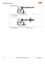
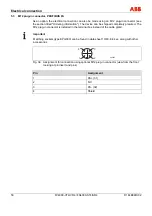
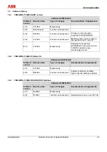
Configuration of the switching output
The switching output can be configure as both a NAMUR contact and an optocoupler.
G00720
1 K
10 K
41
42
41
42
Rotary switch counterclockwise: NAMUR
contact
Rotary switch clockwise: optocoupler
Fig. 37: Switching output circuit diagram
The switching output of the transmitter is factory-configured on the basis of the order code. The
following table lists contact types and their matching order codes and Ex approval.
Order code
Ex approval
Contact type
VT40, VR40, ST40, SR40
None
optocoupler
VT41,VR41, ST41, SR41
Ex ib / Ex nA [nL]
NAMUR contact
VT42, VR42, ST42, SR42
Ex d / Ex ib / Ex nA [nL]
Optocoupler
VT43, VR43, ST43, SR43
C
FM
US
Optocoupler
VT4A, VR4A, ST4A, VR4A
II 2G EEx ia IIC T4
NAMUR contact
If necessary, the switching output can be modified subsequently should prevailing site
conditions change.
1.
Disconnect the flowmeter from the line supply.
2.
Unscrew the front housing cover. The lock on the cover needs to be undone first on meters
for hazardous areas.
Important
Observe the waiting times for meters for hazardous areas (see the section titled "Technical
data for hazardous areas").
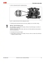
3.
Remove the transmitter from the housing. To do this, unscrew the three Phillips head screws
and carefully take the transmitter out of the housing.
Содержание FS4000-SR4
Страница 1: ...Operating Instruction D184B097U02 Vortex Flowmeter Swirl Flowmeter FV4000 VT4 VR4 FS4000 ST4 SR4 ...
Страница 125: ...Appendix D184B097U02 FV4000 VT4 VR4 FS4000 ST4 SR4 125 ...
Страница 126: ...Appendix 126 FV4000 VT4 VR4 FS4000 ST4 SR4 D184B097U02 ...
Страница 127: ...Appendix D184B097U02 FV4000 VT4 VR4 FS4000 ST4 SR4 127 ...
Страница 128: ...Appendix 128 FV4000 VT4 VR4 FS4000 ST4 SR4 D184B097U02 ...
Страница 129: ...Appendix D184B097U02 FV4000 VT4 VR4 FS4000 ST4 SR4 129 ...
Страница 135: ......


