


70
EL3000
CONTINUOUS GAS ANALYZERS | OI/EL3000-EN REV. D
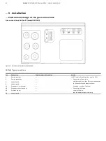
… 5 Installation
… Position and design of the gas connections
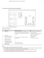
Gas connections Magnos206 (model EL3040)
Figure 21:
Gas connections Magnos206 (model EL3040)
Magnos206: Gas Connections
Pos.
Connection
Supplementary information
Version
1
Sample gas inlet
—
⅛ NPT female thread (stainless steel 1.4305)
• Connection of hose lines:
straight screw-in socket (PP) with hose nozzles for
hoses with inside diameter 4 mm
(included in scope of delivery)
• Connection of piping:
screw-in fittings
(not included in scope of delivery)
2
Sample gas outlet
—
3
Not assigned
—
4
Not assigned
—
11
Purge gas inlet
(housing)
—
12
Purge gas outlet
(housing)
—
13
Pressure sensor
—
14
Not assigned
—
Note
The pressure sensor (see
on page 36) is installed as an option.
For a precise pressure correction as well as for measurements in suppressed measuring ranges, the sensor and sample gas outlet
have to be connected to each other via a T-piece and with the use of short conductors.
The lines must be as short as possible or – in the case of a greater length – have a sufficiently large inside diameter (min. 10 mm) so
that the flow effect is minimized.


