


1.0 INTRODUCTION
1.1 General
1.1.1 Description
The Series 3000 Magnetic Flowmeter is a compact, volumetric, liquid flow rate detector that uses as
the process transducing method the characteristic of a conductive liquid to generate an induced
voltage when flowing through a magnetic field. The amplitude of the voltage produced is directly
proportional to the flow rate of the metered liquid.
Being a completely obstructionless metering instrument, the meter may be used with many non-ho-
mogeneous liquids and is as independent of the tendency to plug or foul as the pipeline in which it is
mounted. An inherent advantage of obstructionless construction is that pressure losses are reduced
to levels occurring in equivalent lengths of equal diameter pipeline. This reduces or conserves
pressure source requirements in new or existing hydraulic lines as compared to other metering
methods. The compact size of the meter results in a light-weight unit which requires no additional
support other than that used normally on pipe runs. Short laying lengths minimize the need for
altering existing pipe runs to accommodate metering. A basic construction of corrosion resistant
wetted parts and a variety of meter lining materials permit metering of most corrosive and reactant
liquids.
Factors such as liquid viscosity and density require no compensation and have no effect on the
measurement accuracy of the meter. Metering limitations are confined to a minimum threshold of
electrical conductivity inherent to the liquid being metered. The degree of liquid conductivity has no
effect upon metering accuracy as long as it is greater than this minimum level. Liquid temperature is
limited only to the extent that it may affect liquid conductivity, and liquid pressure to the extent that it
can not exceed the meter material specification limits.
For information applicable to the signal converter, refer to the signal converter instruction bulletin.
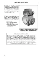
1.1.2 Construction
The meter consists of a flanged, stainless steel pipe spool which serves as a meter body. A pair of
flat magnet coils are installed on opposite sides of the meter housing inner surface. Permeable iron
straps and pole pieces focus the magnetic field generated by the coils and provide a flux return path.
An interior liner of Hard Rubber, Soft Rubber, TEFLON
®
(PTFE), TEFZEL
®
(ETFE), neoprene,
polyurethane, or LINATEX
is assembled into the spool and formed against the flange faces. Two
cylindrical electrodes are mounted diametrically opposed within the central portion of the meter body
and are completely insulated from the metal pipe. The end surfaces of the electrodes are virtually
flush with the inner surface of the insulating liner and come into contact with the liquid to be metered.
10DS3111E INSTRUCTION MANUAL
1-1
Содержание COPA-XM 3000 Series
Страница 24: ...FIGURE 2 5 OUTLINE DIMENSIONS 6 12 INCH FLOWMETER WITH ANSI FLANGES HI TEMP 10DS3111E INSTRUCTION MANUAL 2 8 ...
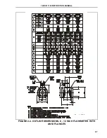
Страница 25: ...FIGURE 2 6 OUTLINE DIMENSIONS 1 4 INCH FLOWMETER WITH DIN FLANGES Ref 10D4288 10DS3111E INSTRUCTION MANUAL 2 9 ...
Страница 26: ...FIGURE 2 7 OUTLINE DIMENSIONS 6 12 INCH FLOWMETER WITH DIN FLANGES 10DS3111E INSTRUCTION MANUAL 2 10 ...
Страница 27: ...FIGURE 2 8 OUTLINE DIMENSIONS 6 12 INCH FLOWMETER WITH DIN FLANGES HI TEMP 10DS3111E INSTRUCTION MANUAL 2 11 ...
Страница 34: ...FIGURE 2 14 GASKET LOCATIONS CBI 3007 10DS3111E INSTRUCTION MANUAL 2 18 ...
Страница 40: ...FIGURE 2 19 CONDUIT ENTRY SEAL INSTALLATION ...


