


6.3.2 Electrode Check
The electrode check is essentially a resistance measurement that can be made to establish that a
short (or high resistance leakage path) does not exist between one, or both, electrodes and the meter
body. Verify that the system power service has been de-energized.
To perform this test, the meter must be removed from the pipeline and the meter liner thoroughly
dried. When the meter liner has been dried, proceed as follows:
1) Disconnect and identify(tag) the electrode signal leads, 1 and 2, from the terminal
board in the signal converter (or from the terminal board in the base of the meter
housing).
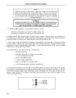
2) Place ohmmeter on highest available range (for example: R x 100,000).
3) Connect the ohmmeter "minus" lead to the meter ground stud and the "plus" lead
to electrode line 1. This reading should be infinite. If any resistance can be measured,
the meter is defective and must be replaced.
4) Check the other electrode by connecting the ohmmeter "plus" lead to line 2. This
reading must also be infinite. If any resistance can be measured, the meter is
defective and must be replaced.
5) If measurement of both electrodes indicate an infinite resistance reading, the meter
may then be returned to on-stream operation. LINES 1 AND 2 FROM THE RESPEC-
TIVE ELECTRODES MUST BE RECONNECTED TO TERMINALS 1 AND 2 OF THE
TERMINAL BOARD. DO NOT INTERCHANGE THESE PROCESS SIGNAL CON-
NECTIONS.
10DS3111E INSTRUCTION MANUAL
6-4
Содержание COPA-XM 3000 Series
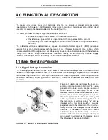
Страница 24: ...FIGURE 2 5 OUTLINE DIMENSIONS 6 12 INCH FLOWMETER WITH ANSI FLANGES HI TEMP 10DS3111E INSTRUCTION MANUAL 2 8 ...
Страница 25: ...FIGURE 2 6 OUTLINE DIMENSIONS 1 4 INCH FLOWMETER WITH DIN FLANGES Ref 10D4288 10DS3111E INSTRUCTION MANUAL 2 9 ...
Страница 26: ...FIGURE 2 7 OUTLINE DIMENSIONS 6 12 INCH FLOWMETER WITH DIN FLANGES 10DS3111E INSTRUCTION MANUAL 2 10 ...
Страница 27: ...FIGURE 2 8 OUTLINE DIMENSIONS 6 12 INCH FLOWMETER WITH DIN FLANGES HI TEMP 10DS3111E INSTRUCTION MANUAL 2 11 ...
Страница 34: ...FIGURE 2 14 GASKET LOCATIONS CBI 3007 10DS3111E INSTRUCTION MANUAL 2 18 ...
Страница 40: ...FIGURE 2 19 CONDUIT ENTRY SEAL INSTALLATION ...


