


6.3 Static Test
If improper operation of the meter is suspected, the following resistance measurements can be made
to establish whether an electrical malfunction has occurred. An analog multimeter is required for
checking the electrodes. Either an analog or digital multimeter can be used for checking the coils.
These measurements can be made at the flowmeter pc board.
WARNING
Equipment that operates from ac line voltage constitutes a potential
electric shock hazard to the user. Make certain that the system power is
disconnected before making the following ohmmeter checks.
6.3.1 Magnet Coil Check
6.3.1.1 Signal Converter
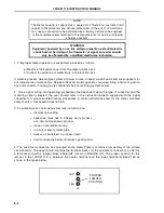
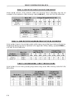
Verify that the system power service has been de-energized. Turn off the power to the signal
converter to de-energize the meter. Remove cable leads M1 and M2/M3 from the customer terminal
block. Measure magnet coil series resistance by connecting the ohmmeter between M1 and M2/M3.
The value displayed should correspond to that indicated in Table 6-1. A reading of infinity or a short
circuit between leads indicates defective coil(s). If proper coil resistance is verified, reconnect cable
leads to terminals M1 and M2/M3. If coil(s) is defective, meter must be returned to the factory for
service.
TABLE 6 -1. METER COIL RESISTANCE
Meter Size
Coil Resistance
Nominal, ohms
±
20%
inches
mm
Each
Coil
Series
Resistance *
1
25
156
312
1
1
⁄
2
40
240
480
2
50
190
380
3
80
110
220
4
100
74
148
6
150
11
22
8
200
10.7
21.4
10
250
10.7
21.4
12
300
10.7
21.4
* M1 to M3
Reference temperature = 60
o
C
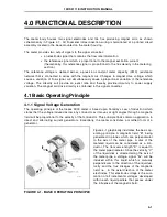
10DS3111E INSTRUCTION MANUAL
6-3
Содержание COPA-XM 3000 Series
Страница 24: ...FIGURE 2 5 OUTLINE DIMENSIONS 6 12 INCH FLOWMETER WITH ANSI FLANGES HI TEMP 10DS3111E INSTRUCTION MANUAL 2 8 ...
Страница 25: ...FIGURE 2 6 OUTLINE DIMENSIONS 1 4 INCH FLOWMETER WITH DIN FLANGES Ref 10D4288 10DS3111E INSTRUCTION MANUAL 2 9 ...
Страница 26: ...FIGURE 2 7 OUTLINE DIMENSIONS 6 12 INCH FLOWMETER WITH DIN FLANGES 10DS3111E INSTRUCTION MANUAL 2 10 ...
Страница 27: ...FIGURE 2 8 OUTLINE DIMENSIONS 6 12 INCH FLOWMETER WITH DIN FLANGES HI TEMP 10DS3111E INSTRUCTION MANUAL 2 11 ...
Страница 34: ...FIGURE 2 14 GASKET LOCATIONS CBI 3007 10DS3111E INSTRUCTION MANUAL 2 18 ...
Страница 40: ...FIGURE 2 19 CONDUIT ENTRY SEAL INSTALLATION ...


