


2.5 Grounding Procedure
2.5.1 General
Satisfactory operation of metering system requires that careful attention be paid to proper grounding
techniques. A good ground is one that is in contact with the earth over a large conductive area. An
excellent example of this is a metallic cold water pipe which is underground. A great number of pipe
branches form a large conductive area of contact which provides a low resistance connection to
earth. A hot water or steam pipe must first return to a boiler before it becomes a cold water pipe, and
therefore, its greater length of ungrounded path offers a less desirable ground bus. A metallic
structural member of a building, such as a supporting "
I
" beam, may be a good earth ground, but it
is a second choice to a metallic cold water pipe.
Flowmeter grounding requirements are a combination of standard grounding methods and a bonding
of the meter body to the process liquid. The most important of these is the process bonding, which is
ensuring that the meter body is in contact with the process liquid at both ends of the meter body. The
bonding procedure places an electrical short circuit across the meter, thereby routing any stray
current around the liquid in the meter (rather than through it).
From the point of view of grounding there are two basic types of piping systems:
•
electrically conductive pipeline: the process liquid comes in contact with conductive
pipe. This piping requires that each meter flange be connected with a bonding wire
to the adjacent pipeline flange. The grounding procedure to use with conductive
pipeline is described in 2.5.2.
•
non-conductive or electrically insulated pipeline: the pipeline may be made of an
electrically non-conductive material (plastic, concrete, etc.) or lined with a
non-conductive material (rubber, TEFLON, etc). These non-conductive pipelines
require the use of metal grounding rings to bond the process liquid to ground. The
grounding procedure to use with nonconductive pipeline is described in 2.5.3.
Proper grounding of the meter is required for optimum system performance.
10DS3111E INSTRUCTION MANUAL
2-20
Содержание COPA-XM 3000 Series
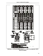
Страница 24: ...FIGURE 2 5 OUTLINE DIMENSIONS 6 12 INCH FLOWMETER WITH ANSI FLANGES HI TEMP 10DS3111E INSTRUCTION MANUAL 2 8 ...
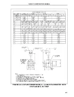
Страница 25: ...FIGURE 2 6 OUTLINE DIMENSIONS 1 4 INCH FLOWMETER WITH DIN FLANGES Ref 10D4288 10DS3111E INSTRUCTION MANUAL 2 9 ...
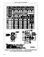
Страница 26: ...FIGURE 2 7 OUTLINE DIMENSIONS 6 12 INCH FLOWMETER WITH DIN FLANGES 10DS3111E INSTRUCTION MANUAL 2 10 ...
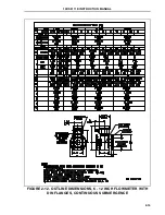
Страница 27: ...FIGURE 2 8 OUTLINE DIMENSIONS 6 12 INCH FLOWMETER WITH DIN FLANGES HI TEMP 10DS3111E INSTRUCTION MANUAL 2 11 ...
Страница 34: ...FIGURE 2 14 GASKET LOCATIONS CBI 3007 10DS3111E INSTRUCTION MANUAL 2 18 ...
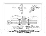
Страница 40: ...FIGURE 2 19 CONDUIT ENTRY SEAL INSTALLATION ...


