


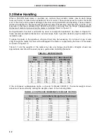


2.2 Meter Handling
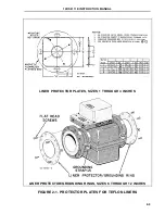
When a TEFLON lined meter is specified, two optional liner protector plates (one on each flange
face) are factory installed (when specified at time of order). These plates serve to contain the flared
ends of the liner, and to prevent damage to the liner during installation and handling. These protector
plates are attached to the meter with flat head screws that securely hold the liner in place. If the
pressure on the liner is relieved, the TEFLON will tend to curl away from the flange. These protector
plates must remain in place when the meter is installed. Refer to Figure 2-1.
During shipment, the liner is protected by wood or composition protectors as shown in Figure 2-2;
these are removed before the meter is installed; leave them in position while moving the meter to the
installation site.
To place the meter in the pipeline a sling and hoist may be necessary. Do not pass a rope or wire
sling through the meter; the liner will be damaged if the meter is supported by the liner. Lift the meter
as shown in Figure 2-2.
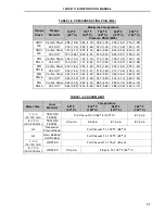
Table 2-1 lists the weights of the meters by size and flange classification. Weights shown are
approximate and should be used only as a guide when installing the meter.
TABLE 2-1. METER WEIGHTS
Meter
Size
ANSI Class 150
DIN PN10-16
ANSI Class 300
DIN PN25-40
Inches
mm
lbs
kg
lbs
kg
1
25
8
3.5
19
8.4
1
1
⁄
2
40
12
5.3
23
10.1
2
50
16
7.1
27
11.9
3
80
26
11.5
36
15.9
4
100
37
16.3
51
22.5
6
150
70
32
140
64
8
200
155
70
210
95
10
250
220
100
295
134
12
300
275
125
365
166
If the continuous submergence option is chosen for Model 10DS3111, the meter weights shown
above must be modified by adding the weights shown in the following table:
TABLE 2-2. CONTINUOUS SUBMERGENCE WEIGHT FACTORS
Meter Size
Add to Meter Weight from Table Above
Inches
mm
lbs
kg
1
25
1.01
.46
1
1
⁄
2
40
0.96
.44
2
50
1.04
.47
3
80
1.08
.49
4
100
1.92
.87
6
150
11.23
5.1
8
200
15.57
7.1
10
250
23.27
10.6
12
300
50.47
22.9
10DS3111E INSTRUCTION MANUAL
2-2
Содержание COPA-XM 3000 Series
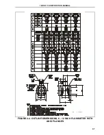
Страница 24: ...FIGURE 2 5 OUTLINE DIMENSIONS 6 12 INCH FLOWMETER WITH ANSI FLANGES HI TEMP 10DS3111E INSTRUCTION MANUAL 2 8 ...
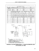
Страница 25: ...FIGURE 2 6 OUTLINE DIMENSIONS 1 4 INCH FLOWMETER WITH DIN FLANGES Ref 10D4288 10DS3111E INSTRUCTION MANUAL 2 9 ...
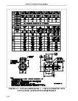
Страница 26: ...FIGURE 2 7 OUTLINE DIMENSIONS 6 12 INCH FLOWMETER WITH DIN FLANGES 10DS3111E INSTRUCTION MANUAL 2 10 ...
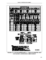
Страница 27: ...FIGURE 2 8 OUTLINE DIMENSIONS 6 12 INCH FLOWMETER WITH DIN FLANGES HI TEMP 10DS3111E INSTRUCTION MANUAL 2 11 ...
Страница 34: ...FIGURE 2 14 GASKET LOCATIONS CBI 3007 10DS3111E INSTRUCTION MANUAL 2 18 ...
Страница 40: ...FIGURE 2 19 CONDUIT ENTRY SEAL INSTALLATION ...


