background image

2

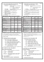
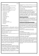
Additional information relating to cULus approval:

For use in Pollution Degree 2 Environment

Information complémentaire relative à la certification cULus:

Pour utilisation dans un environnement de degré de pollution 2


Technical data

CM-IWN.1

Ambient temperature T

a

 during operation 

-25 ... +60 °C (-13 ... +140 °F)

Pollution degree

3

Degree of protection                   housing

IP50

terminals

IP20

according to EN/IEC 61557-8

Internal impedance Zi at 50 Hz

min.

155 kOhm

Peak value of Um

24 V +10 %

Max. value of Im

0.15 mA

Max. system leakage capacitance Ce

20 μF

Max. DC voltage Ufg

460 V DC

Test voltage

supply circuit / output circuit

2.32 kV 50 Hz, 2 s

supply circuit / measuring circuit

2.32 kV 50 Hz, 2 s

measuring circuit / output circuit

2.53 kV 50 Hz, 1 s

Electrical data for the contact circuits and the interface

Min. switching voltage / current

24 V / 10 mA

Max. switching voltage / current

see load limit curves in data sheets

Rated operational current (EN/IEC 60947-5-1)

AC12 (resistive) 230 V

4 A

AC15 (inductive) 230 V

3 A

DC12 (resistive) 24 V

4 A

DC13 (inductive) 24 V

2 A

Internal resistance Ri of the 
measuring circuit

min.

185 kOhm

(ZH) 

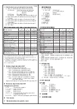
֡ፕᇑҾጎኸళ


CM

ဣଚਨᇹ॔๫ीۉഗ

ጀᅪǖ

Ԩ֡ፕኸళփԈࡤरຍຕ਍ࢅඇևᆌᆩຫ௽Lj໯ᆶຕ

਍ኻ๟ਏᆶܔׂ೗༬Ⴀ৊ႜຫ௽ڦፕᆩLjᅺُփਏԢ݆ୱၳ
ᆌăၘဦຫ௽൩֖ለरຍᄣԨई૴ஏ

ABB

ړںӸ๚تई៓બ

BCCྪበDŽ

www.abb.com

Džăසᆶ߸߀ທփཚኪăժᅜڤ࿔

ྺՔጚă

য়ߢƽླ၃ۉუƽৈ੗ᆯۉഘጆᄽටᇵҾጎ൐Ⴔޙ
ࢇ༬ۨڦࡔॆࡀۨDŽස

VDE

ڪDžăҾጎമLj൩ጮဦ൐

ඇևለ܁޿Ҿጎຫ௽ă࿮Ք๎ڦ܋ጱփ੗থ၍ă

2CDC 253 013 F0014

2CDC 253 012 F0014

COV.12 - 

1SVR 750 005 R0100

3

4

1

2

2

2CDC 253 0 01  F0016

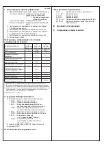
(DE)

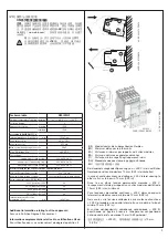
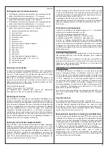
Mindestabstände zu benachbarten Geräten

(EN)

Minimum distances to other units

(FR)

Distances minimales par rapports à d’autres modules

(ES)

Distancia mínima con aparatos cercanos

(IT)

Distanze minime rispetto agli apparecchi vicini

(RU)

Минимальное расстояние до других блоков

(ZH)

ᇑഄ໲ఇ੷ڦፌၭक़ਐ

Bei dauernd anliegender Spannung von > 400 V ist ein seitlicher 
Geräteabstand von mindestens 10 mm (0,39 in) einzuhalten!

In case of continuous measured voltage > 400 V, lateral spacing to 
other units has to be min. 10 mm (0.39 in)!

Dans le cas d‘une tension permanente mesurée > 400 V, 
l‘espacement latérale par rapport aux autres modules doit être de 
10 mm (0,39 in) au minimum!

Para tensiones de medida continuas > 400 V dejar un espacio 
lateral entre módulos como mínimo de 10 mm (0,39 in)!

Nel caso in cui la tensione sottoposta a misura fosse di continuo 
> 400 V, prevedere uno spazio laterale tra un modulo e l‘altro di 
minimo 10 mm (0,39 in)!

В случае непрерывного измерения напряжения

 > 400 

В, 

расстояние до других блоков в поперечном направлении 

должно составлять не менее 10 мм (0.39 дюймов)!

ړ૶Ⴤ֪ଉۉუ!

> 400 V

้Lj၎ତఇ੷ڦक़ਐፌၭᆌྺ

10 mm

DŽ

0.39 in

Džƽ
Содержание CM Series

Страница 1: ... prescriptions nationales p e VDE etc Avant l installation de cet appareil veuillez lire l intégralité de ces instructions Ne pas connecter de conducteur aux bornes non marquées Printed in Germany Doc no 1SVC 750 020 M0000 C 01 2016 ES Instrucciones de servicio y de montaje Relés de control de aislamiento serie CM Nota Estas instrucciones no contienen todas las informaciones detalladas relativas a...

Страница 2: ... ፕᆩLjᅺُփਏԢ ୱၳ ᆌăၘဦຫ ൩ ለरຍᄣԨई ஏABB ںړ Ӹ ت ई બ BCCྪበDŽwww abb comDžăසᆶ ߀ທփཚኪăժᅜ ڤ ྺՔጚă য়ߢƽླ၃ ۉ უƽৈ ᆯ ۉ ഘጆᄽටᇵҾጎ Ⴔ ޙ ࢇ ۨ ۨࡀॆࡔڦ DŽසVDE ڪ DžăҾጎമLj൩ጮဦ ඇևለ Ҿጎຫ ă Ք ڦ ጱփ থ ă 2CDC 253 013 F0014 2CDC 253 012 F0014 COV 12 1SVR 750 005 R0100 3 4 1 2 2 2CDC 253 0 01 F0016 DE Mindestabstände zu benachbarten Geräten EN Minimum distances to other units FR Distances minimales par rapports à d autres modules ES Distancia ...

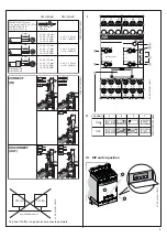
Страница 3: ... x 0 5 1 5 mm 1 x 18 14 AWG 2 x 18 16 AWG 2 x 0 5 1 5 mm 2 x 18 16 AWG 8 mm 0 315 DIN 46228 1 A DIN 46228 4 E CM IWN xS CM IWN xP 2CDC 253 005 F0012 I 햲 햴 햳 R1 2 value kȍ R1 1 value kȍ A1 11 21 S1 S2 S3 L 12 14 L 24 22 V1 VS V1 A2 KE F U R CM IWN R1 1 value k R1 1 value k R2 1 value kȍ R2 2 value kȍ Rx Rx 1 Rx 2 Test Reset 100 80 20 60 14 12 10 8 60 50 40 30 4 5 6 7 햸 햷 햵 햶 II Position 4 1 2 3 ON ...

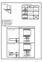
Страница 4: ...088 F0b09 2CDC 252 086 F0b09 A1 11 S2 S3 21 S1 w L VS 12 14 A2 V1 V1 22 24 L KE 2CDC 252 086 F0b09 A1 11 S2 S3 21 S1 w L VS 12 14 A2 V1 V1 22 24 L KE Un C 400 V AC Un C 600 V DC CM IWN x Un max 400 V AC 600 V DC 1 2 wire AC system 2 wire DC system DE Verdrahtungsdiagramme EN Wiring diagrams FR Schémas de câblage ES Esquemas de cableado IT Schemi di cablaggio RU Схемы соединения ZH থ 1 For monitori...

Страница 5: ... L3 N PE 2CDC 252 096 F0b09 Un C 400 V AC Un C 400 V AC Un C 600 V DC 2CDC 252 100 F0b09 A1 11 S2 S3 21 S1 w L VS 12 14 A2 V1 V1 22 24 L KE 2CDC 252 093 F0b09 A1 11 S2 S3 21 S1 w L VS 12 14 A2 V1 V1 22 24 L KE 2CDC 252 093 F0b09 A1 11 S2 S3 21 S1 w L VS 12 14 A2 V1 V1 22 24 L KE Always connect L and L to different conductors L and L can be connected to any of the conductors 3 wire AC system 4 wire...

Страница 6: ...y 2 VS V1 V1 Connection for coupling unit CM IVN S1 S2 S3 Control inputs volt free triggering IV Remote test V Fault storage and reset Deutsch I Frontansicht mit Bedienelementen 햲 Betriebszustandsanzeige mit LEDs U LED grün Anzeige der Steuerspeisespannung V Steuerspeisespannung liegt an F LED rot Fehlermeldung R LED gelb Anzeige der Schaltstellung der Aus gangsrelais 햳 Einstellung der 10er Stelle...

Страница 7: ...N S1 S2 S3 Entrées de commande activation libre de potentiel IV Test à distance V Mémorisation de défaut et réinitialisation Español I Vista frontal con elementos de mando 햲 Indicadores de servicio con LEDs U LED verde Indicación tensión de alimentación de mando V Tensión de alimentación de mando aplicada F LED rojo Mensaje de error R LED amarillo Indicación estado de los relés de salida 햳 Ajuste ...

Страница 8: ...el valore di soglia più l isteresi 4 A seconda del guasto II Funzioni degli interruttori DIP 햸 Interruttori DIP per l impostazione di 1 ON Funzionamento normalmente chiuso OFF Funzionamento normalmente aperto 2 ON Memorozzazione dei guasti non volatile ON OFF Memorozzazione dei guasti non volatile OFF 3 ON Rilevamento di interruzione cavi ON OFF Rilevamento di interruzione cavi OFF 4 ON 2 valori d...

Страница 9: ...за после сохра нения информации об отказе 3 V 4 X 1 В зависимости от конфигурации смотрите функциональные схемы 2 Возможная неправильная настройка Пороговое значение срабатывания реле должно быть выше чем значение предварительного предупреждения 3 Устройство сработало после повреждения изоляции Информация об отказе была сохранена а сопротивление изоляции вернулось к уровню превы шающему пороговое ...

Страница 10: ...10 ...

Страница 11: ...le h U green LED F red LED R yellow LED U green LED F red LED R yellow LED 2CDC 252 053 F0209 Closed circuit principle g ts Start up time fixed min 15 s A1 A2 S1 S3 S2 S3 ts ts 11 12 11 14 21 22 21 24 11 12 11 14 21 24 21 24 Measured value Hysteresis Threshold value Open circuit principle h U green LED F red LED R yellow LED U green LED F red LED R yellow LED 2CDC 252 054 F0209 Closed circuit prin...

Страница 12: ...ED F red LED R yellow LED U green LED F red LED R yellow LED 2CDC 252 055 F0209 Closed circuit principle g ts Start up time fixed min 15 s A1 A2 S1 S3 S2 S3 ts ts 11 12 11 14 21 22 21 24 11 12 11 14 21 24 21 24 Measured value Hysteresis Prewarning Hysteresis Warning Open circuit principle h U green LED F red LED R yellow LED U green LED F red LED R yellow LED 2CDC 252 056 F0209 Closed circuit prin...

Страница 13: ...13 ...

Страница 14: ... größer dem eingestellten Schwellwert plus Hysterese bzw den eingestellten Schwellwerten plus Hysteresen ist Die Fehlerspeicherung ist nullspannungssicher remanent ausgeführt Das heißt nach Abschalten und Wiederkehr der Steuerspeisespannung geht das Gerät in den Zustand der vor dem Abschalten vorhanden war über bis ein Reset durchgeführt wird Deutsch VI Funktionsdiagramme a Isolationswiderstandsüb...

Страница 15: ...he insulation resistance is higher than the set threshold value s plus hysteresis The fault storage is designed non volatile remanent This means that after switch off and return of the control supply voltage the device returns to the state it was prior to the switch off until a reset is executed English VI Function diagrams a Insulation resistance monitoring without fault storage auto reset 1 x 2 ...

Страница 16: ...S2 S3 si la résistance d isolement dépasse la valeur de seuil réglée plus l hystérésis ou les valeurs de seuil réglées plus les hystérésis Il s agit d une mémorisation de défaut à la coupure d alimentation rémanente Cela signifie que après mise à l arrêt et rétablissement de la tension d alimentation de commande l appareil reprend l état qu il avait avant la mise à l arrêt jusqu à ce qu une réiniti...

Страница 17: ...o de error y no volverán a su posición original antes de que se pulse el botón combinado Test Reset o se realice el reset a distancia terminales S2 S3 La memoria de fallo es una memoria no volátil remanente Esto quiere decir que después de desconectar y reconectar la tensión de alimentación de mando el aparato conmutará al estado precedente al corte de tensión es decir antes de que se realizara el...

Страница 18: ...to morsetti S2 S3 a condizione che la resistenza di isolamento sia maggiore del valore di soglia impostato più l isteresi ovvero dei valori di soglia impostati più le isteresi La memorizzazione dei guasti non è volatile per assenza di tensione Ciò significa che scollegando e ricollegando la tensione di comando l apparecchio ritorna nello stato in cui si trovava prima dello spegnimento fino all esecu...

Страница 19: ...ния информации об отказах является энергонезависимой постоянного действия Это означает что после выключения и возврата напряжения питания управления устройство вернется в состояние в котором оно находилось до выключения и будет находиться в этом состояния до выполнения сброса Русский VI Функциональные схемы a Контроль сопротивления изоляции без сохранения информации об отказах автоматический сброс...

Страница 20: ...Lj2x1 c o ۅة 햲 ੦ ࠃ ۉۉ უ 햳 ᇺ ײ 햴 ᇺ ްײ 햵 ଉኵ 햶 ው 햷 ពኵ 햸 ਸୟᇱሶ 햹 ी ۉ ഗ1 햺 ी ۉ ഗ2 햻 LED 햽 ࢤ LED 햾 ࣜ LED 햿 Կୟᇱሶ 헀 ഔ ۯ क़tsLjፌၭ15sLjࠦۨ 헁 ᇨԒয় 헂 Ԓয় ࠀీ ӀቷIEC 61557 8LjCM IWN 1 ᆩᇀ փথ ں IT ୁဣཥĂᇑ ୁ ୟ ۉټ থ ڦ IT ୁဣཥĂईփথ ں IT ୁဣཥă ړ ଉ ڟ ဣཥ ۉ ᇸ ࢅဣཥথ ں ኮक़ ڦ ਨᇹ ۉ ፆ گ ᇀยۨ ڦ ពኵ DŽពኵ ۙDžLj ी ۉ ഗൎ ࠤڟ ቱጒༀă ଉ ୟ ۉ უ ǖ 0 600 V DC ई 0 400 V AC 15 400 Hz ఇ ᆩᇀ ੦ ୟDŽ ڇ Džࢅዷ ୟDŽ3 Džă ଉᇱ CM IWN xࣷ ᅃ ࡀሶ ڦ ஞ ଉ႑ࡽ ڟ ԥ ڦ ဣཥዐLj ࢫਨᇹ ۉ ፆ ᅜԥऺ໙ ઠăኄ ࡀሶ ڦ...

Отзывы: