


- 12 -
006CC2
2 - Plan the installation
E
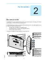
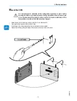
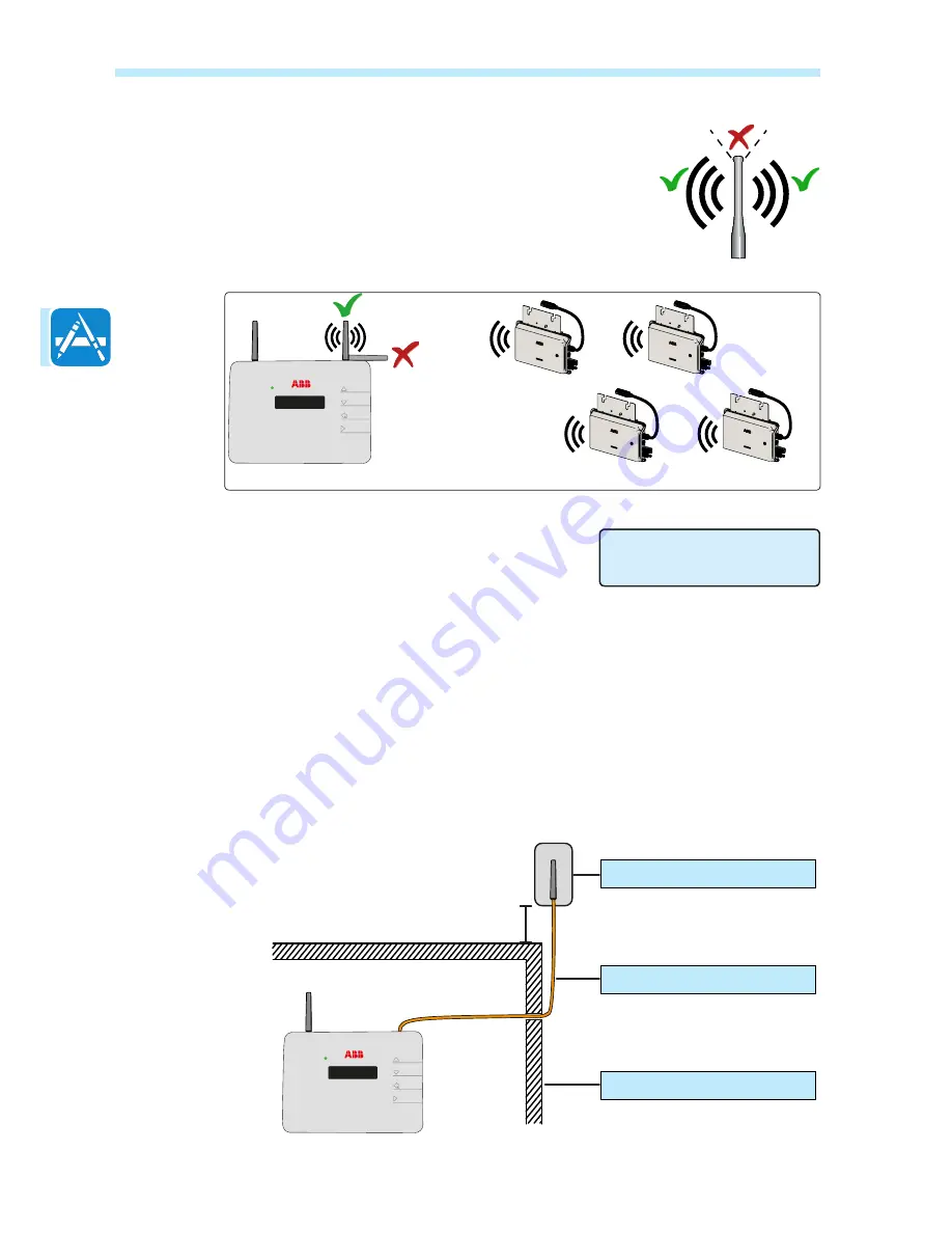
valuate the installation position
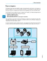
The radio signal can be limited by obstacles and distance.
In order to boost the signal strength, position the antenna of the CDD in a parallel
line to the inverters. The antenna has a deadzone at the tip that should not be facing
the inverters.
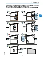
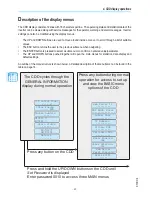
When configuring the CDD and acquiring the
inverters in part 4 and 5, it may be necessary to
adjust the positioning of the antenna. The RF signal
quality is shown in the CDD display (see part 3).
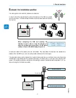
An extension cable for the antenna can also be installed. The cable allows the antenna to be installed at a
distance from the CDD to go over or around possible obstacles to the radio signal.
The extended antenna can be installed in an outdoor rated plastic box (see technical note online
“Improving
CDD Wireless Signal Reception”
for detailed instructions), 15cm/6in above a roof and in line-of-sight of PV
panels. The extended antenna could also use the existing conduits of residential electrical systems or TV an-
tennas to bring the CDD antenna outside.
CDD
Plant quality
High (65%)
CDD
15cm / 6in
Radio Antenna
Antenna ExtensionCable
Radio signal obstacle
Содержание CDD
Страница 1: ...ABB solar inverters Product manual CDD concentrator data device ...
Страница 6: ... 6 002TC ...
Страница 26: ... 26 010CC4 4 CDD display operations ...
Страница 32: ... 32 011CC5 5 Acquire the MICRO inverters ...


