


Guidelines for planning the electrical installation 71
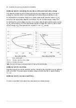
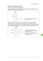
IImplementing the Power loss ride-through function
Implement the power loss ride-through function as follows:
1. Check that the power-loss ride-through function of the drive is enabled with parameter
30.31 Undervoltage control
in the ACS880 primary control program.
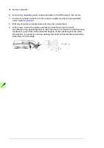
2. If the installation is equipped with a main contactor, prevent its tripping at the input
power break. For example, use a time delay relay (hold) in the contactor control circuit.
WARNING!
Make sure that the flying restart of the motor will not cause any
danger. If you are in doubt, do not implement the power-loss ride-through
function.
Using power factor compensation capacitors with the
drive
Power factor compensation is not needed with AC drives. However, if a drive is to be
connected in a system with compensation capacitors installed, note the following
restrictions.
WARNING!
Do not connect power factor compensation capacitors or harmonic
filters to the motor cables (between the drive and the motor). They are not
meant to be used with AC drives and can cause permanent damage to the drive
or themselves.
If there are power factor compensation capacitors in parallel with the three phase input of
the drive:
1. Do not connect a high-power capacitor to the power line while the drive is connected.
The connection will cause voltage transients that may trip or even damage the drive.
2. If capacitor load is increased/decreased step by step when the AC drive is connected
to the power line, ensure that the connection steps are low enough not to cause
voltage transients that would trip the drive.
3. Check that the power factor compensation unit is suitable for use in systems with AC
drives, ie, harmonic generating loads. In such systems, the compensation unit should
typically be equipped with a blocking reactor or harmonic filter.
Implementing a safety switch between the drive and the
motor
We recommended that you install a safety switch between the permanent magnet motor
and the drive output. The switch is needed to isolate the motor during any maintenance
work on the drive.
Содержание ACS880-07XT Series
Страница 1: ...ABB industrial drives Hardware manual ACS880 07XT drives 400 to 1200 kW ...
Страница 4: ......
Страница 12: ...12 ...
Страница 20: ...20 Safety instructions ...
Страница 26: ...26 Introduction to the manual ...
Страница 47: ...Mechanical installation 47 Moving the crate with a forklift Free width for fork tines 750 mm 29 5 ...
Страница 54: ...54 Mechanical installation ...
Страница 89: ...Electrical installation 89 PE 11 8 4 9 11 ...
Страница 94: ...94 Electrical installation ...
Страница 110: ...110 Start up Test and validate the operation of Prevention of unexpected start with FSO xx option Q950 Action ...
Страница 112: ...112 Fault tracing ...
Страница 123: ...Maintenance 123 5 6 7 ...
Страница 124: ...124 Maintenance 8 10 9 ...
Страница 126: ...126 Maintenance 6 5 4 ...
Страница 127: ...Maintenance 127 9 8 7 ...
Страница 128: ...128 Maintenance 12 11 10 ...
Страница 149: ...Dimensions 149 Dimension drawing examples Frame 2 R11 R10 with brake chopper ...
Страница 150: ...150 Dimensions Frame 2 R11 R10 without brake chopper ...
Страница 153: ...Dimensions 153 Location of input terminals ACS880 07XT 12 pulse ...
Страница 154: ...154 Dimensions Location of output terminals ACS880 07XT R10 with du dt ...
Страница 155: ...Dimensions 155 Location of output terminals ACS880 07XT R10 without du dt ...
Страница 156: ...156 Dimensions Location of output terminals ACS880 07XT R11 with du dt ...
Страница 157: ...Dimensions 157 Location of output terminals ACS880 07XT R11 without du dt ...
Страница 158: ...158 Dimensions Location of PE terminals ACS880 07XT ...
Страница 159: ...Dimensions 159 Location of resistor terminals ACS880 07XT R10 ...
Страница 160: ...160 Dimensions Location of resistor terminals ACS880 07XT R11 ...
Страница 168: ...www abb com drives www abb com drivespartners 3ABD00043579 Rev C EN 2018 01 01 Contact us ...