


Guidelines for planning the electrical installation 67
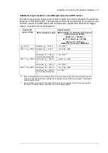
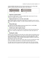
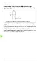
A double-shielded cable (figure a below) is the best alternative for low-voltage digital
signals but single-shielded (b) twisted pair cable is also acceptable.
Signals in separate cables
Run analog and digital signals in separate, shielded cables. Never mix 24 V DC and
115/230 V AC signals in the same cable.
Signals allowed to be run in the same cable
Relay-controlled signals, providing their voltage does not exceed 48 V, can be run in the
same cables as digital input signals. The relay-controlled signals should be run as twisted
pairs.
Relay cable type
The cable type with braided metallic screen (for example ÖLFLEX by LAPPKABEL,
Germany) has been tested and approved by ABB.
Control panel cable length and type
In remote use, the cable connecting the control panel to the drive must not exceed three
meters (10 ft). Cable type: shielded CAT 5e or better Ethernet patch cable with RJ-45
ends.
Routing the cables
Route the motor cable away from other cable routes. Motor cables of several drives can be
run in parallel when installed next to each other. The motor cable, input power cable and
control cables should be installed on separate trays. Avoid long parallel runs of motor
cables with other cables in order to decrease electromagnetic interference caused by the
rapid changes in the drive output voltage.
Where control cables must cross power cables, make sure they are arranged at an angle
as near to 90 degrees as possible. Do not install extra cables through the drive.
The cable trays must have good electrical bonding to each other and to the grounding
electrodes. Aluminum tray systems can be used to improve local equalizing of potential
a
b
Содержание ACS880-07XT Series
Страница 1: ...ABB industrial drives Hardware manual ACS880 07XT drives 400 to 1200 kW ...
Страница 4: ......
Страница 12: ...12 ...
Страница 20: ...20 Safety instructions ...
Страница 26: ...26 Introduction to the manual ...
Страница 47: ...Mechanical installation 47 Moving the crate with a forklift Free width for fork tines 750 mm 29 5 ...
Страница 54: ...54 Mechanical installation ...
Страница 89: ...Electrical installation 89 PE 11 8 4 9 11 ...
Страница 94: ...94 Electrical installation ...
Страница 110: ...110 Start up Test and validate the operation of Prevention of unexpected start with FSO xx option Q950 Action ...
Страница 112: ...112 Fault tracing ...
Страница 123: ...Maintenance 123 5 6 7 ...
Страница 124: ...124 Maintenance 8 10 9 ...
Страница 126: ...126 Maintenance 6 5 4 ...
Страница 127: ...Maintenance 127 9 8 7 ...
Страница 128: ...128 Maintenance 12 11 10 ...
Страница 149: ...Dimensions 149 Dimension drawing examples Frame 2 R11 R10 with brake chopper ...
Страница 150: ...150 Dimensions Frame 2 R11 R10 without brake chopper ...
Страница 153: ...Dimensions 153 Location of input terminals ACS880 07XT 12 pulse ...
Страница 154: ...154 Dimensions Location of output terminals ACS880 07XT R10 with du dt ...
Страница 155: ...Dimensions 155 Location of output terminals ACS880 07XT R10 without du dt ...
Страница 156: ...156 Dimensions Location of output terminals ACS880 07XT R11 with du dt ...
Страница 157: ...Dimensions 157 Location of output terminals ACS880 07XT R11 without du dt ...
Страница 158: ...158 Dimensions Location of PE terminals ACS880 07XT ...
Страница 159: ...Dimensions 159 Location of resistor terminals ACS880 07XT R10 ...
Страница 160: ...160 Dimensions Location of resistor terminals ACS880 07XT R11 ...
Страница 168: ...www abb com drives www abb com drivespartners 3ABD00043579 Rev C EN 2018 01 01 Contact us ...