Electrical installation
66
Fastening the control cables and covers
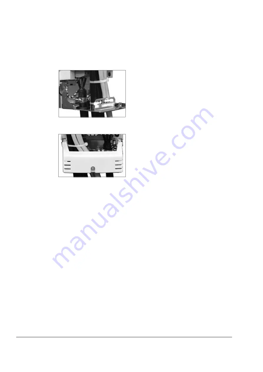
When all control cables are connected, fasten them together with cable ties. Units
with a connection box: fasten the cables to the entry plate with cable ties. Units with
a gland box: tighten the clamping nuts of the cable glands.
Fasten the connection box cover.
Replace the front cover.
Installation of optional modules and PC
The optional module (such as fieldbus adapter, I/O extension module and the pulse
encoder interface) is inserted in the optional module slot of the RMIO board (see
) and fixed with two screws
.
See the appropriate
optional module manual for cable connections.
Note:
Two RDCO modules are provided for the DDCS fibre optic link between the
RMIO boards of the line-side and motor-side converters. Channel CH0 of the
RDCO-03 module in the line-side converter and channel CH1 of the RDCO module
in the motor-side converter are used for the internal communication. In case multiple
devices are to be connected to one channel, they must be connected in a ring.
Ex24 V power supply for the RMIO board
Refer to chapter
Содержание ACS800-11
Страница 1: ...ACS800 Hardware Manual ACS800 11 Drives 5 5 to 110 kW ACS800 U11 Drives 7 5 to 125 HP ...
Страница 4: ......
Страница 12: ...Safety instructions 12 ...
Страница 30: ...The ACS800 11 U11 30 ...
Страница 36: ...Mechanical installation 36 ...
Страница 54: ...Planning the electrical installation 54 ...
Страница 59: ...Electrical installation 59 1 2 3 Views of frame size R5 U1 V1 W1 V2 W2 U2 UDC UDC 5 5 PE 6 6 8 9 9 ...
Страница 74: ...Installation checklist 74 ...
Страница 84: ...Operation 84 ...
Страница 104: ...Technical data 102 ...
Страница 105: ...Dimensional drawings 103 Dimensional drawings The dimensions are given in millimetres and inches ...
Страница 108: ...Dimensional drawings 106 ...
Страница 111: ...External 24 V power supply for the RMIO board 109 5 6 7 8 ...
Страница 112: ...External 24 V power supply for the RMIO board 110 ...
Страница 113: ......


