Chapter 6 – Service and Maintenance
ACS 501 Installation & Start-up Manual
6-13
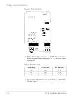
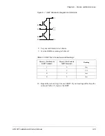
Table 6-4 Meter Connections
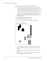
Figure 6-6 Motor Control Card
Meter (+) Test Probe
Meter (-) Test Probe
Reading
G1
X3:W2
1.5
G1
X2:(+)
1.5
G2
X3:V2
1.5
G2
X2:(+)
1.5
G3
X3:U2
1.5
G3
X2:(+)
1.5
G4
X3:W2
1.2
G4
X2:(-)
1.2
G5
X3:V2
1.2
G5
X2:(-)
1.2
G6
X3:U2
1.2
G6
X2:(-)
1.2
G6
G5
G3
G2
G1
G4
Motor Control Card
R11
X9
X7
X8
X6
R3
W1
V1
U1
Line Input
X1
X2
X3
M
3 ~
+
-
U2 V2 W2
L1
L2
L3
Brake
Chopper
Содержание ACS 501
Страница 8: ...Table of Contents ACS 501 Installation Start up Manual vii Glossary G 1 Index I 1 ...
Страница 9: ...Table of Contents viii ACS 501 Installation Start up Manual This page intentionally left blank ...
Страница 13: ...Chapter 1 Introduction 1 4 ACS 501 Installation Start up Manual This page intentionally left blank ...
Страница 47: ...Chapter 4 Start up Procedure 4 8 ACS 501 Installation Start up Manual This page intentionally left blank ...
Страница 71: ...Chapter 6 Service and Maintenance 6 16 ACS 501 Installation Start up Manual This page intentionally left blank ...

