background image

Chapter 3 – Installation Instructions

ACS 501 Installation & Start-up Manual

3-15

X50

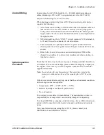
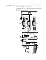
Terminal Block X50 can accept wire sizes from 16 – 22 AWG. All 
connections to terminals X50:1 to X50:20 should be made with shielded 
cables.

X50:2, 4, 6, 8, 18, and 20 are circuit common. They are optically isolated 
from the power line potential and from chassis ground by a 10 megohm 
resistor. The common points are not isolated from each other.

Note: The ACS 501 is shipped with a wire from X50:8 to chassis ground, or 

with a jumper labeled S9 next to X50. This connects the circuit common 
to chassis ground. To isolate the circuit common from ground, remove 
this connection.

Potentiometer

A manual speed potentiometer is connected to the reference at X50:1 (+ 10 
VDC) and X50:2 (common) and to one of the analog inputs.

Analog Inputs

There are two analog inputs. AI1 is on terminals X50:3 and X50:4. AI2 is on 
X50:5 and X50:6.

The analog inputs can accept a voltage signal (0 – 10 VDC) or a current signal 
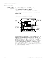
(0 – 20 mA), as selected by jumpers S1 and S2 (S1 for AI1 and S2 for AI2).

The jumper is placed in the V position for voltage and the I position for 
current. Figure 3-8 shows jumper positions.

Note: The orientation of the jumpers may be different than the illustration 

below. Settings should be made based on the identification on the 
circuit board.

Figure 3-8

Jumper Positions

Auxiliary 24 VDC

An aux24 VDC supply is available on terminals X50:7 and X50:8. 
This supply can drive auxiliary devices whose total current draw is less than 
200 mA.

Digital Inputs

There are six digital inputs, DI1 through DI6 on terminals X50:11 through 
X50:16 respectively. The digital inputs use 24 VDC logic from terminal 
X50:10 and are active high.

Analog Outputs

There are two analog output signals. AO1 is on terminals X50:17 and X50:18. 
AO2 is on X50:19 and X50:20. These signals are 0 – 20 mA (or 4 – 20 mA) 
and can operate into a maximum 500 ohm load.

V

I

V

I

Voltage

Current

Содержание ACS 501

Страница 1: ...ACS 501 ABB Drives Installation Start up Manual ASEA BROWN BOVERI ACS 501 Adjustable Frequency AC Drives 1 to 75 HP Series B ACS 501 04E EFFECTIVE 7 1 95 SUPERCEDES 9 1 94 ...

Страница 2: ... 1995 ABB Drives Inc All Rights Reserved ACS 501 Adjustable Frequency AC Drives 1 to 75 HP Series B Installation Start up Manual ACS 501 04E EFFECTIVE 1995 07 01 SUPERCEDES 1994 09 01 ...

Страница 3: ... 1995 ABB Drives Inc All Rights Reserved ACS 501 Adjustable Frequency AC Drives 1 to 75 HP Series B Installation Start up Manual ACS 501 04E EFFECTIVE 1995 07 01 SUPERCEDES 1994 09 01 ...

Страница 4: ...s or conditions which will damage machinery or cause additional motor operation down time if you do not take suggested steps to correct or address such situations or conditions Note Notes provide you with additional and useful information Although less urgent than cautions and warnings notes are important and should not be ignored Warning Symbols For your own safety please pay special attention to...

Страница 5: ...ry out the electrical installation Note that the Motor Control Card of the ACS 501 is at DC bus voltage potential The DC bus capacitors contain dangerous DC voltage levels 1 35 x VIN After disconnecting the supply wait at least five minutes after the display readout on the control panel has disappeared before taking any measurements Dangerous external control voltages may be present on the relay o...

Страница 6: ...eneral Information About Your ACS 501 2 2 Features and Functions 2 2 Control Panel Operation 2 5 Control Panel Display 2 5 Control Panel Keys 2 6 Application Macros Overview 2 8 Chapter 3 Installation Instructions Grounding and Ground Faults 3 1 Pre Installation Planning 3 1 Environment 3 2 Mounting Area 3 3 Installation Site Power 3 5 Conduit Size 3 5 Power Wiring 3 6 Output Power Wiring 3 7 Cont...

Страница 7: ...ult Tracing Fault Indications 5 1 Fault Resetting 5 1 Fault History 5 2 Fault Erasing 5 2 Fault Tracing 5 3 Warning Messages 5 3 Fault Messages 5 4 Chapter 6 Service and Maintenance Electrostatic Discharge Precautions 6 1 Rectifier Tests 6 1 ACS 501 002 003 and 005 6 2 ACS 501 007 to 040 6 3 DC Bus Capacitor Tests 6 6 ACS 501 002 003 and 005 6 7 ACS 501 007 to 040 6 9 IGBT Module Tests 6 11 ACS 50...

Страница 8: ...Table of Contents ACS 501 Installation Start up Manual vii Glossary G 1 Index I 1 ...

Страница 9: ...Table of Contents viii ACS 501 Installation Start up Manual This page intentionally left blank ...

Страница 10: ...501 describes drive components and provides a brief introduction to Control Panel operation the drive parameter menu system and drive Application macros Chapter 3 Installation Instructions describes planning for drive installation new drive inspection and drive mounting This chapter also includes requirements and connections for input and output wiring and external control wiring Chapter 4 Start u...

Страница 11: ...rameters into four main functional groups A Main in this manual is the number corresponding to Group access All Groups in the 10s range are accessed on the Control Panel through CONTROL CONNECTIONS MAIN 10 Access Groups in the 20s range through DRIVE PARAMETERS MAIN 20 Access Groups in the 30s range through PROTECTION PARAMETER MAIN 30 and access Groups in the 40 s range through APPLIC PARAMETERS ...

Страница 12: ...ilures due to misuse abuse improper installation or abnormal conditions of temperature dust or corrosives or failures due to operation above rated capacities Nor shall the manufacturer ever be liable for consequential and incidental damages The period of manufacturer s warranty is 12 months and not more than 18 months from the date of delivery Extended warranty may be available with certified star...

Страница 13: ...Chapter 1 Introduction 1 4 ACS 501 Installation Start up Manual This page intentionally left blank ...

Страница 14: ...Type S Standard Product Family 50 ACS 500 Construction 1 Sizes 001 to 060 Wall Mounted 2 Sizes 050 to 300 Std Floor Stand Cabinet 4 Sizes 050 to 300 Module Output Power HP Constant Torque Input Voltage 3 380 415 VAC 4 440 500 VAC Internal Option 2 3 Bus Adapter Card SNAT 7610 BAC Internal Option 1 8 5 Isolated Digital Inputs SNAT 763 DII 9 3 15 PSI and 2 Isolated Digital Inputs SNAT 762 PSI 0 No O...

Страница 15: ...n place of the DC choke Note The maximum number of chargings in one minute is four In applications where frequent start stop is required electronic start stop should be used with the unit powered continuously The Inverter Stage forms symmetrical three phase AC voltage from the constant DC voltage supplied by the DC Intermediate Circuit A Motor Control Card controls the Inverter Stage and monitors ...

Страница 16: ... 3 4 3 1 3 0 4 8 4 3 6 2 R2 ACS501 003 4 3 0 4 8 4 3 5 0 7 6 6 8 7 5 ACS501 005 4 5 0 7 6 6 8 7 5 11 0 9 9 10 0 ACS501 007 4 7 5 11 0 9 9 10 0 14 0 12 6 13 2 R3 ACS501 010 4 10 0 14 0 12 6 15 0 21 0 18 9 18 0 ACS501 015 4 15 0 21 0 18 9 20 0 27 0 24 3 24 0 R4 ACS501 020 4 20 0 27 0 24 3 25 0 34 0 30 6 31 0 ACS501 025 4 25 0 34 0 30 6 30 0 40 0 36 0 38 0 R5 ACS501 030 4 30 0 40 0 36 0 40 0 52 0 46 ...

Страница 17: ... Analog Outputs Program Digital Inputs Program Analog Inputs X50 X51 X56 X55 Communication with PC PLC etc Communication with Motor Control Application Control Control Interface Motor Control Inverter Control Power Supply Measurements T Gate Drivers I V DC M 3 φ GND W2 V2 U2 V out Motor Connection Brake Connection Line Connection V in W1 V1 U1 GND 3 φ 3 φ See Note Note 600 volt units have AC choke...

Страница 18: ...layed in nine languages English German Italian Spanish Dutch French Danish Finnish and Swedish The language selection is made in Start up Data Parameter A Language Figure 2 3 shows control panel display indications Figure 2 3 Control Panel Displays Main Name Rotation Direction Forward Reverse Main Number Control Location Keypad Control No Brackets External Run Status I Run O Stop Parameter Number ...

Страница 19: ... Reference Function Selects the Setting mode and saves the selected parameter value Right Arrow Left Arrow Steps between levels Selects between Operating Data Main Group and Parameter levels and In Setting Mode returns to the Display mode without changing the Parameter value Up Arrow Down Arrow Steps through choices within a level In Display mode selects the next previous Main Group or Parameter a...

Страница 20: ...y Up Arrow and Down Arrow key Change to Setting mode Brackets indicate that the parameter value now can be changed Set the parameter value If you want to cancel the change and return to Display mode press Right Arrow or Left Arrow otherwise Save the selected value to parameter memory Brackets disappear indicating that the parameter value is stored in memory Return to Operating Data Parameter 1 Out...

Страница 21: ...nd 86 F 15 C and 30 C Application Macros Overview Application macros are complete sets of default parameter settings for some typical applications This allows all of the parameters to be set with the touch of a button When you select an Application macro the parameters listed in the ACS 500 Adjustable Frequency AC Drives 2 to 350 HP Programming Manual Including Application Macros are set to a valu...

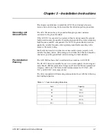
Страница 22: ...d faults occurring in the motor or the motor wiring Fault current protective switches do not necessarily operate properly with variable frequency drives When using such switches their function should be checked at possible ground fault currents arising in a fault situation Pre Installation Planning The ACS 500 has been short circuit tested in accordance with UL508 The R3 R5 5 drives are suitable f...

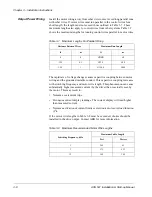
Страница 23: ...t IRSQ The cooling air must be clean and free from corrosive materials When necessary the required cooling should be provided by using clean dry air Table 3 2 Required Cooling Air Volume for ACS 501 Units If the cooling air contains dust clean the cooling surfaces of the unit regularly using compressed air and a brush If the ACS 501 is in a NEMA 1 enclosure cover the vents to prevent the dust from...

Страница 24: ...t the bottom See Figure 3 1 for the space requirements If units are to be mounted next to each other each unit must have two inches 50 mm of clear space so that a total of four inches 100 mm between two units is available for proper cooling If units are mounted one above the other at least 12 inches 300 mm is required between the units At least three 3 separate grounded conduits are required One e...

Страница 25: ... Start up Manual Figure 3 2 shows the ACS 501 with dimensions coded by letters Table 3 3 lists the actual dimensions for each ACS 501 unit The table shows dimensions in inches and mm Figure 3 2 ACS 501 Dimensions Side C D a H H2 b W1 W H1 Bottom Front Ht Ht1 Ht2 ...

Страница 26: ...600 VAC W 7 7 8 200 9 55 64 250 11 13 16 300 13 13 16 351 13 13 16 351 W1 5 29 32 150 6 57 64 175 8 55 64 225 10 27 32 275 10 27 32 275 H 14 17 64 362 16 3 4 425 19 31 32 507 23 3 4 603 23 3 4 603 H1 13 25 32 350 15 3 4 400 18 29 32 480 22 41 64 575 22 41 64 575 H2 12 9 32 312 14 31 32 380 18 7 64 460 21 45 64 551 21 45 64 551 D 7 25 64 188 8 3 16 208 9 13 16 249 10 5 16 262 12 1 16 307 a 15 64 7 ...

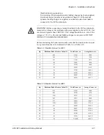
Страница 27: ...R5 drive and conduit sizes to fit wire entry holes Figure 3 5 ACS 501 R5 R5 5 Conduit Sizes Power Wiring All field wiring shall be copper conductor rated for 140 F 60 C and torqued to the values in Table 3 4 Table 3 4 Wire Torque Values Table 3 5 indicates the minimum and maximum wire sizes allowable for each size unit Unit in lbs Nm R2 R3 8 8 1 R4 R5 R5 5 17 6 2 1 2 in 3 4 in 1 in 25 4 mm 19 0 mm...

Страница 28: ...ACS501 040 4 ACS501 020 2 R5 100 8 AWG 0 AWG ACS501 050 4 060 4 ACS501 025 2 030 2 ACS501 040 6 050 6 R5 5 160 8 AWG 0 AWG Drive Type Unit Rating Mfg Type ACS501 002 4 005 4 ACS501 001 2 002 2 R2 16A 500V Bussmann FWH 16A6F Ferraz 500V FA 6 3 x 32 16 ACS501 007 4 010 4 ACS501 003 2 005 2 ACS501 005 6 007 6 R3 30A 600V Bussmann FWC 30A10F Ferraz 6 600 CP URL 10 3 x 38 30 ACS501 015 4 020 4 ACS501 0...

Страница 29: ... grounded metallic conduit This capacitive coupling increases with switching frequency and motor wire length This phenomenon can cause substantially higher measured current by the drive than is actually seen by the motor This may result in Nuisance overcurrent trips Erroneous current display readings The current display will read higher than measured current Nuisance activation of current limits o...

Страница 30: ...ons section description of X50 in this chapter for an outline of control signal requirements when selecting an Application macro Initial Inspection Procedure Check that the drive does not show any signs of damage and that the delivery is complete In the event of damage please contact the shipping company or the supplier If the delivery is not in compliance with the order contact the supplier immed...

Страница 31: ...s 600 volt units only Attach the leads from the ac choke to the input terminals in the base drive at the input fuses and connect the leads from the output terminal block to the output terminals in the drive All field connections are made to the terminal blocks in the ac choke enclosure Input Wiring The ACS 501 is designed for use on a three phase system Four wires three phase plus a ground wire ar...

Страница 32: ...ng chopper is not present DO NOT CONNECT LOAD BANK RESISTORS Before connecting the brake resistor make sure that the resistor value is equal to or greater than the value indicated in Table 3 9 or Table 3 10 Table 3 9 Resistor Values For 230 V Table 3 10 Resistor Values For 480 V hp Minimum Brake Resistor Value Ω Peak Power w AveragePower w 1 25 8 4446 2223 2 16 0 7171 3586 3 12 1 9465 4733 5 8 9 1...

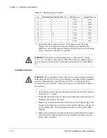
Страница 33: ... check that the ACS 501 is disconnected from incoming line power Failure to disconnect line power could result in death or serious injury 1 Check that the motor wires are disconnected from the ACS 501 output on Terminals U2 V2 and W2 2 Check that the motor wires are disconnected from the motor and remove bridging connections at the motor 3 Measure the insulation resistances of the motor The voltag...

Страница 34: ...AA AA AA AA AA AA ACS 501 002 005 Motor Control Card Line Connection U1 V1 W1 L1 L2 L3 U2 V2 W2 U1 V1 Motor 3φ Brake Unit Option Brake Connection Motor Connection X3 X2 GND Heatsink X1 L1 L2 L3 Ground Line Input W1 GND A A AAAAAAAAAA Metallic Conduit Conduit for Metallic Conduit Control Wires if used Metallic Conduit AA AA AA AA AA AA AA AA AA AA AA AA AA AA AA AA AA AA AA AA AA AA AA AA AA AA AA ...

Страница 35: ...nnection diagram of each Application macro or according to the programming of the parameters in Main 10 Control Connections The connection diagrams of Application macros are presented in the ACS 500 Adjustable Frequency AC Drives 2 to 350 HP Programming Manual Including Application Macros The X50 connection diagram based on factory settings is presented in Figure 3 7 Control Interface Card SNAT 75...

Страница 36: ...d X50 4 AI2 is on X50 5 and X50 6 The analog inputs can accept a voltage signal 0 10 VDC or a current signal 0 20 mA as selected by jumpers S1 and S2 S1 for AI1 and S2 for AI2 The jumper is placed in the V position for voltage and the I position for current Figure 3 8 shows jumper positions Note The orientation of the jumpers may be different than the illustration below Settings should be made bas...

Страница 37: ...ssion must be provided at the load This is to reduce the electrical noise that could interfere with the electronics in the drive as well as increase the life of the contacts in the relay AC coils should be supressed with an MOV metal oxide varistor or a Series Connected RC resistor capacitor network as illustrated below MOV should be rated 120 VAC 240 VAC for 115 VAC circuits 240 VAC 320 VAC for 2...

Страница 38: ... corresponds to 0 60 Hz Motor current 0 20 mA corresponds to 0 IMAX Relay output 1 Ready indication Relay output 3 Fault Inv indication A A AAAAAAAAAAAAAAAAAAAAAAAAAA A A AAAAAAAAAAAAAAAAAAAAAAAAAA A A A A AAAA AAAA AAAA AAAA AAAA AAAA AAAA AAAA AA AA A A A A AAAA AAAAAAAA AAAAAAAA AAAAAAAA AAAAAAAA AAAAAAAA AAAAAA AA A A A A A A A A A A A A A A A A A A A A A A A A A A A A A A A A A A A A A A A A ...

Страница 39: ...Chapter 3 Installation Instructions 3 18 ACS 501 Installation Start up Manual This page intentionally left blank ...

Страница 40: ...safe measure the voltage between positive and negative on Terminal Block X2 labeled Brake Meter must be rated for 1000 VDC Note If the internal brake option is installed measure between the input terminal block X1 and positive on Terminal Block X2 Meter must be rated for 1000 VDC The Control Interface Card and Option Cards are isolated from the main circuit but dangerous voltages may be present at...

Страница 41: ...onnections wire shields grounding location as far as possible from the power wires Quantity and quality of cooling air for the ACS 501 Verify that it is safe to run the motor Connect the ACS 501 to supply voltage Check that the voltage between L1 L2 L2 L3 and L1 L3 U1 V1 U1 W1 and V1 W1 is VN 10 PREPARATION SAFETY PRECAUTIONS Read and follow safety instructions INSTALLATION INSPECTION Check for pr...

Страница 42: ...o YES by pressing Up Arrow Press to confirm the selection and move to the next parameter D SUPPLY VOLTAGE This parameter offers choices of 440 460 480 and 500 VAC for 480 volt units 380 400 and 415 VAC for 380 volt units or 208 220 230 and 240 VAC for 230 volt units Press Up Arrow or Down Arrow to select the voltage value which matches the line voltage providing power to your ACS 501 Press to conf...

Страница 43: ... to 500 Hz in 10 Hz increments Changing this value will automatically set the FWP to the same value Press Up Arrow or Down Arrow to select the base frequency value for your motor Press to confirm the selection and move to the next parameter J MOTOR BASE R P M This parameter is used to set the nameplate speed of the motor and is adjustable from 200 to the maximum 2 pole motor speed based on Start u...

Страница 44: ...tor on the LCD Display displays the symbol 5 Press to enter setting mode Press Up Arrow until frequency display shows 60 Hz then press to enter value 6 Press Up Arrow or Down Arrow to scroll through and check the Operating Data parameters Check that Operating Data Parameter 7 Output Voltage is equal to the input voltage If the drive operates according to these steps disconnect and lock out power t...

Страница 45: ...on is critical and the motor does not run in the direction indicated by the Rotation Direction indicator on the ACS 501 LCD Display shut down the drive disconnect and lock out power to the drive wait five minutes and check for zero volts at Terminals X50 21 29 and X2 and When the drive has reached zero volts swap any two motor output wires at Terminals U2 V2 and W2 Incorrect motor rotation directi...

Страница 46: ...e macro to custom fit your application For example if you select the Factory macro for your application the Factory macro default for Start up Data Parameter D Supply Voltage is 480 V If your supply voltage is 460 V you need to change this parameter in the macro accordingly To customize the macro for your application you must change certain parameter values In each macro certain parameters are mor...

Страница 47: ...Chapter 4 Start up Procedure 4 8 ACS 501 Installation Start up Manual This page intentionally left blank ...

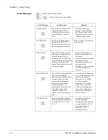
Страница 48: ...play warning indications which indicate abnormal operation but do not cause the drive to stop If a fault occurs when a warning display is on the warning will be erased and the fault indication is displayed Figure 5 1 shows examples of warning and fault indications Figure 5 1 Warning and Fault Indications Fault Resetting A fault can be reset either by pressing the Keypad Start Stop button activatin...

Страница 49: ... trips the deceleration time should be longer Scrolling through the Fault History parameters does not erase the Fault History The oldest fault or warning is automatically erased when a new fault or warning occurs Note Undervoltage Fault and Supervision Limit Indications are not stored in Fault History They remain on display until reset by pressing Start Stop or by external fault reset The source o...

Страница 50: ... Refer to Fault 3 Mot Stall in the next section 3 MOTOR TEMP Parameter 30 1 3 Mot Temp Flt Func is set to WARNING Refer to Fault 4 Mot Temp in the next section 6 UNDER LOAD Parameter 30 1 10 Underload Func is set to WARNING Refer to Fault 7 Under Load in the next section 7 AI MIN Parameter 30 1 2 AI Min Func is set to WARNING Refer to Fault 11 AI Min in the next section 8 EEPROM WR Parameter stori...

Страница 51: ...e mechanical problem causing increased load torque If the motor shaft is rotating and the motor is not overheating increase stall limit parameters Check drive sizing use larger ACS 501 and motor if necessary 4 MOTOR TEMP The ACS 501 determined that the motor is overheated Because the temperature rise is calculated from the motor current and not measured directly the motor may be within temperature...

Страница 52: ...the supply voltage loss of phase or brown out condition Check supply voltage If supply voltage was adequate an internal failure has occurred Contact ABB Technical Support 11 AI MIN Analog input is less than the minimum as set by Parameters 10 5 1 and 10 5 5 Input reference has failed or control wire is broken Check the reference circuit 16 PWR RNGE Power range programming does not match after repl...

Страница 53: ...set fault display the display is reset allowing the scrolling of parameters but the fault is not reset Check all parameter settings or restore the factor settings Remove power wait one minute then restore power to check that the fault has disappeared 23 UNDER V 2 DC bus voltage does not rise over 93 of VN during five seconds after connecting the input power Check supply voltage Call ABB Technical ...

Страница 54: ... ACS 501 Temp Warning Fault Check ambient temperature per chart below Check cooling air flow Air flow OK Heat fins dusty Clear restrictions to air flow Clean dust from heatsink fins Ambient temperature 104 F Restart system and check for faults Re size ACS 501 for this application or add extra cooling Internal fault Contact ABB Technical Support No Yes Yes No Yes No No Yes Ambient temperature 104 F...

Страница 55: ...nect ACS 501 from input power Motor short circuit ground fault Cable short circuit ground fault Reconnect ACS 501 to input line power Restart system Overcurrent trip again Remove mechanical fault Restart system Yes No Yes Check and or replace motor Check and or replace cable Reconnect ACS 501 to input line power Restart system Check for faults Yes No No Yes Internal fault Contact ABB Technical Sup...

Страница 56: ...d against this type of damage when circuit boards are removed or installed Wear a wrist type grounding strap that is grounded to the chassis Attach the wrist strap before removing the new circuit board or IGBT from the conductive packet Remove components from the drive and immediately insert them into their conductive packets Rectifier Tests The Rectifier Tests are divided into groups according to...

Страница 57: ...mark the wires to correspond to their component and terminal connections 3 Remove all control wiring from the Control Interface Card Note Terminal Block X50 disconnects from the Control Interface Card in three whole sections To do this lift the interlocking tabs along the top edge of the three X50 sections and carefully pry the sections straight outward from the Control Interface Card Mark the sec...

Страница 58: ... from these resistance values replace the Rectifier Module ACS 501 007 to 040 Diode Test 1 Disconnect and lock out power from the ACS 501 WARNING Wait at least five minutes after disconnecting power from the drive before you attempt to service the drive Bus capacitors in the intermediate circuit must discharge before servicing the drive Check for zero volts at Terminals X50 21 29 and X2 and or bet...

Страница 59: ...tor Control Card and swing the Control Interface Card open to access the Motor Control Card 5 Remove all wires from the rectifier terminals 6 Set your multimeter to test diodes If your multimeter does not have a diode test function refer to the Resistance Test following this Diode Test 7 Connect the multimeter negative test probe to the rectifier positive terminal and measure each rectifier phase ...

Страница 60: ...le Resistance Test 1 Follow Diode Test Steps 1 5 above 2 Set your multimeter to test resistance If your multimeter has a diode test function disregard the Resistance Test and continue with Diode Test Steps 6 10 above 3 Measure the rectifier as in Diode Test Steps 7 10 above The meter should register a range from 100 to 10 000 ohms and infinity accordingly 4 Connect the multimeter positive test pro...

Страница 61: ...group requires two separate tests one for capacitor resistance and one for capacitor DC insulation These tests tells you if your DC bus capacitors need replacement Damaged electrolytic capacitors may withstand 300 V while not operating at normal power levels A resistance test together with a Meggar test for DC insulation reveals enough information to determine the condition of electrolytic capacit...

Страница 62: ...nstalled CAUTION Electrostatic Discharge ESD can damage electronic circuits Do not handle any components without following the proper ESD precautions Note When disconnecting wires from components and terminals mark the wires to correspond to their component and terminal connections 3 Remove all control wiring from the Control Interface Card Note Terminal Block X50 disconnects from the Control Inte...

Страница 63: ...Readings within ten percent tolerance of listed values are acceptable Table 6 1 Resistance Values 7 If your readings differ from the values in the table above contact ABB Technical Support ACS 501 Rating R3 Value Ohms R11 Value Ohms 002 220k 220k 003 100k 100k 005 100k 100k G6 G5 G3 G2 G1 G4 Motor Control Card R11 X9 X7 X8 X6 R3 W1 V1 U1 Line Input X1 X2 X3 M 3 U2 V2 W2 L1 L2 L3 Brake Chopper ...

Страница 64: ...for zero volts at Terminals X50 21 29 and X2 and or between the input terminal block X1 and Terminal Block X2 if an internal brake option is installed Failure to check voltage may result in death or serious injury 2 Check for zero volts at Terminals X50 21 29 and X2 and or between the input terminal block X1 and Terminal Block X2 if an internal brake option is installed CAUTION Electrostatic Disch...

Страница 65: ...de of the Control Interface Card to the ACS 501 chassis disconnect the cable from X4 on the Motor Control Card and swing the Control Interface Card open to access the Motor Control Card 5 Remove all wires from the DC bus capacitors 6 Set your multimeter to measure resistance Figure 6 5 illustrates the ACS 501 007 to 040 Motor Control Card Figure 6 5 Motor Control Card 7 Connect the multimeter posi...

Страница 66: ...tative IGBT Module Tests The DC Bus Capacitor Tests are divided into groups according to drive ratings ACS 501 002 003 and 005 1 Disconnect and lock out power from the ACS 501 WARNING Wait at least five minutes after disconnecting power from the drive before you attempt to service the drive Bus capacitors in the intermediate circuit must discharge before servicing the drive Check for zero volts at...

Страница 67: ...face Card to the ACS 501 chassis disconnect the cable from X4 on the Motor Control Card and swing the Control Interface Card open to access the Motor Control Card 5 Set your multimeter to test diodes 6 Measure according to Table 6 3 and Table 6 4 Table 6 3 represents meter connections to Terminal Blocks X2 and X3 Table 6 3 Meter Connections to Terminal Blocks X2 and X3 Table 6 4 represents meter c...

Страница 68: ...otor Control Card Meter Test Probe Meter Test Probe Reading G1 X3 W2 1 5 G1 X2 1 5 G2 X3 V2 1 5 G2 X2 1 5 G3 X3 U2 1 5 G3 X2 1 5 G4 X3 W2 1 2 G4 X2 1 2 G5 X3 V2 1 2 G5 X2 1 2 G6 X3 U2 1 2 G6 X2 1 2 G6 G5 G3 G2 G1 G4 Motor Control Card R11 X9 X7 X8 X6 R3 W1 V1 U1 Line Input X1 X2 X3 M 3 U2 V2 W2 L1 L2 L3 Brake Chopper ...

Страница 69: ...onnecting wires from components and terminals mark the wires to correspond to their component and terminal connections 3 Remove all control wiring from the Control Interface Card Note Terminal Block X50 disconnects from the Control Interface Card in three whole sections To do this lift the interlocking tabs along the top edge of the three X50 sections and carefully pry the sections straight outwar...

Страница 70: ...o test diodes 9 Test the IGBTs according to Table 6 5 Table 6 5 IGBT Test Connections and Readings 10 Repeat the tests in Step 9 for each IGBT If your readings differ from the values in Table 6 5 replace the IGBT Meter Test Probe to IGBT Terminal Meter Test Probe to IGBT Terminal Reading C E Over E C 0 35 B C Over B E Over B1 E1 B2 C1 E1 E2 C2 E2 ...

Страница 71: ...Chapter 6 Service and Maintenance 6 16 ACS 501 Installation Start up Manual This page intentionally left blank ...

Страница 72: ...rent constant torque 1 0 x IR Continuous Current variable torque 1 0 x IRSQ Maximum Current 1 min every 10 min 1 5 x IN Short Time Overload 2 sec every 1 min 2 0 x IN Overcurrent Trip 3 75 x IN instantaneous 2 65 x IN RMS Field Weakening Point ACS 501 30 500 Hz Field Weakening Point ACS 502 30 180 Hz Continuous Loadability of Motor 100 at rated speed for F class motor Modulation Frequency ACS 501 ...

Страница 73: ... Digital Relay Outputs Three programmable relay outputs Form C contacts Maximum Switching Voltage 300 VDC 250 VAC Maximum Switching Current Power 8 A 24 VDC 0 4 A 250 VDC or 2000 VA 250 VAC Maximum Continuous Current 2 A rms Environmental Limits Ambient Operating Temperature Constant Torque 32 to 113 F 0 to 45 C NEMA 1 fs 3 kHz Constant Torque 32 to 104 F 0 to 40 C NEMA 12 fs 3 kHz Variable Torque...

Страница 74: ...C Bus voltage is 1 35 x Supply Voltage VIN Default A default is a pre programmed value for a parameter When you first install and start your ACS 501 drive all application macro parameter values appearing on the Keypad Display are default settings You may change these default settings in the process of customizing your drive for your particular drive application Digital Input DI The Digital Inputs ...

Страница 75: ...rive trips and on which settings are based Inverter The inverter changes DC power to AC power for application to the motor windings Control of the inverter affords variable frequency and voltage to be applied to the motor for control of motor speed and direction IR Compensation IR Compensation is a parameter that provides the motor with extra torque at motor speeds between 0 1 Hz and the set Field...

Страница 76: ... capacitor and measures the resistance of the insulation system Meggar test results are usually expressed in megohms CAUTION The ACS 501 must not be subjected to testing of this type as damage could result Any wires connected to the ACS 501 MUST be disconnected from the ACS 501 before being subjected to this type of test Memory The ACS 501 memory provides computer storage for program data and inst...

Страница 77: ...hese parameters are one time settings made only during the drive installation process Start up Data parameters are not accessed through the same display levels as Operating Data parameters Main level or Group level Instead you must first view Operating Data Parameter 1 Output Frequency press and hold on the Control Panel Keypad then press Right Arrow Only this procedure accesses Start up Data para...

Страница 78: ...9 restrictions 3 9 sizes 3 9 terminals 3 9 Conventions used in this manual 1 2 Cooling requirements 3 2 D Digital inputs 3 15 Digital outputs 3 16 Dimensions 3 4 Display contrast adjusting 2 8 Display indications 2 5 Drive code nameplate identification 2 1 E Environment 3 2 ESD warning iv F Fault erasing 5 2 history 5 2 indications 5 1 resetting 5 1 warning messages 5 3 Functions descriptions 2 2 ...

Страница 79: ...strictions 3 8 power connections 3 10 power wiring table 3 6 Programming example 2 7 Publications related to this manual 1 3 R Relay outputs 3 16 S Safety instructions general iii grounding 3 1 warning symbols iii Service DC Bus capacitor tests 6 6 IGBT module tests 6 11 precautions 6 1 rectifier tests 6 1 Specifications A 1 Start up default parameters 4 7 inspection 4 2 keypad control 4 5 paramet...

Страница 80: ...ABB Industrial Systems Inc 16250 West Glendale Drive New Berlin WI 53151 Telephone 414 785 3416 Fax 414 785 0397 ASEA BROWN BOVERI ACS 501 04E EFFECTIVE 7 1 95 SUPERCEDES 9 1 94 ...

Отзывы: