22 PEX430
Publication No. PEX430-0HH/1QD
4.1.5
Differential I/O Signals
The PEX430 can be configured (at build time only) to connect 32 differential signal
I/O to the XMC P16 connector or the PMC P14 connector. This configuration is done
by populating different options of zero ohm links.
4.1.6
Single Ended I/O Signals
The PEX430 can be configured (at design time only) to connect up to 6 single ended
I/O signals to any of up to 14 pins on the XMC P16 connector. This configuration is
done using a CPLD.
4.2
Configuration EEPROMs
The PEX430 includes an EEPROM for configuration data for the PCI Express switch
(PEX8532) and an EEPROM for configuration data for the PCI Express-to-PCI bridge
(PEX8114). Th
ese EEPROMs can be programmed ‘in
-
system’ with suitable software
running on an SBC that is connected to the upstream port.
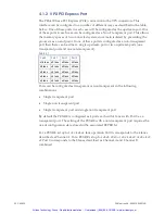
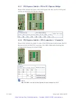
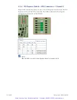
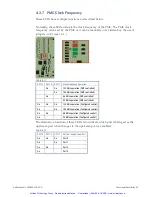
The switch and bridge devices are configured either by ‘strapping’ options (see
below) or at power up from data in the EEPROMs:
If the EEPROMs are blank, or if they are in a Hold mode, the operation of the
PEX8532 and PEX8114 is controlled by options set by the CPLD and jumpers, i.e.
‘strapping’
If the EEPROMs have valid configuration data and they are not in a Hold mode,
the operation of the PEX8532 and PEX8114 is controlled by the data programmed
into the EEPROMs
4.2.1
Recovery Mode
To recover a system with faulty or inappropriate EEPROM contents, the PEX430
should be powered up with the NVMRO signal from the backplane in a logic low
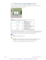
state and jumper E3 pins 1-2 closed (see 3.1.5 ). This puts the EEPROMs into a hold
condition during the boot up phase, which prevents the switch and bridge from
using the EEPROM contents for configuration. Without cycling the power to the
PEX430 remove the jumper form E3 pins 1-2. This removes the hold condition and
allows the EEPROM to be over-written or erased.
Artisan Technology Group - Quality Instrumentation ... Guaranteed | (888) 88-SOURCE | www.artisantg.com


