background image

Publication No. PEX430-0HH/1QD 


Contents  3  

Contents 

1 • Introduction

 .............................................................................................................................. 5


1.1 Features ..................................................................................................................................................................5


1.2 Conventions ............................................................................................................................................................6


1.3 Safety Notices ........................................................................................................................................................7


1.3.1 Safety Summary ................................................................................................................................................................ 7


1.3.2 Power Supplies .................................................................................................................................................................. 7


1.3.3 Backplane Requirements .................................................................................................................................................. 7


1.3.4 Flammability ...................................................................................................................................................................... 7


1.3.5 EMI/EMC Regulatory Compliance .................................................................................................................................... 7


1.3.6 Heatsink ............................................................................................................................................................................. 8


1.4 Abaco Systems Website ........................................................................................................................................8


1.5 Abaco Documents ..................................................................................................................................................8


1.6 Technical Support ..................................................................................................................................................8


1.7 Returns ....................................................................................................................................................................9


2 • Identification and Inspection

 ................................................................................................. 10


2.1 Product Identification ......................................................................................................................................... 10


2.2 Inspection ............................................................................................................................................................ 11


3 • Configuration and Power

-Up .................................................................................................. 12


3.1 Configuration ....................................................................................................................................................... 12


3.1.1 PMC Clock Override (E1) ................................................................................................................................................. 13


3.1.2 PCI Express Port Lane Configuration (E3) ..................................................................................................................... 14


3.1.3 PCI Express Upstream Port Configuration (E1) ............................................................................................................ 14


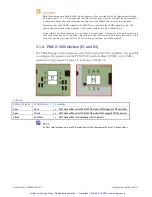
3.1.4 PMC X100 Selection (E1 and E3) ................................................................................................................................... 15


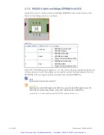
3.1.5 PEX430 Switch and Bridge EEPROM Hold (E3) ............................................................................................................ 16


3.1.6 JTAG Chain (E4) .............................................................................................................................................................. 17


3.2 Power-Up .............................................................................................................................................................. 17


4 • Functional Description

 ........................................................................................................... 18


4.1 Functional Overview ............................................................................................................................................ 18


4.1.1 System Example .............................................................................................................................................................. 19


4.1.2 VPX PCI Express Port...................................................................................................................................................... 20


4.1.3 PCI Express Switch ......................................................................................................................................................... 21


4.1.4 PCI Express to PCI/PCIX Bridge ..................................................................................................................................... 21


4.1.5 Differential I/O Signals .................................................................................................................................................... 22


4.1.6 Single Ended I/O Signals ................................................................................................................................................ 22


4.2 Configuration EEPROMs ..................................................................................................................................... 22


4.2.1 Recovery Mode ................................................................................................................................................................ 22


4.3 LEDs...................................................................................................................................................................... 23


4.3.1 PCI Express Switch > PCI to PCI Express Bridge .......................................................................................................... 24


4.3.2 PCI Express Switch > VPX Connectors 

 Channel A .................................................................................................... 24


4.3.3 PCI Express Switch > VPX Connectors 

 Channel B .................................................................................................... 25


4.3.4 PCI Express Switch > VPX Connectors 

 Channel C .................................................................................................... 26


4.3.5 PCI Express Switch > VPX Connectors 

 Channel D .................................................................................................... 27


4.3.6 PCI Express Switch > XMC Connectors ......................................................................................................................... 28


4.3.7 PMC Clock Frequency ..................................................................................................................................................... 29


4.3.8 Power Supplies ................................................................................................................................................................ 30


4.4 Software ............................................................................................................................................................... 30


4.4.1 Operating Systems .......................................................................................................................................................... 30


4.4.2 BIT 30


Artisan Technology Group - Quality Instrumentation ... Guaranteed | (888) 88-SOURCE | www.artisantg.com

Содержание PEX430

Страница 1: ...l service in house repair center WE BUY USED EQUIPMENT Sell your excess underutilized and idle used equipment We also offer credit for buy backs and trade ins www artisantg com WeBuyEquipment REMOTE INSPECTION Remotely inspect equipment before purchasing with our interactive website at www instraview com LOOKING FOR MORE INFORMATION Visit us on the web at www artisantg com for more information on ...

Страница 2: ...Hardware Reference Manual PEX430 Edition 1QD Publication No PEX430 0HH 1QD Artisan Technology Group Quality Instrumentation Guaranteed 888 88 SOURCE www artisantg com ...

Страница 3: ...ectronic Equipment WEEE Returns Abaco Systems Limited is registered with an approved Producer Compliance Scheme PCS and subject to suitable contractual arrangements being in place will ensure WEEE is processed in accordance with the requirements of the WEEE Directive Abaco Systems Limited will evaluate requests to take back products purchased by our customers before August 13 2005 on a case by cas...

Страница 4: ...h and Bridge EEPROM Hold E3 16 3 1 6 JTAG Chain E4 17 3 2 Power Up 17 4 Functional Description 18 4 1 Functional Overview 18 4 1 1 System Example 19 4 1 2 VPX PCI Express Port 20 4 1 3 PCI Express Switch 21 4 1 4 PCI Express to PCI PCIX Bridge 21 4 1 5 Differential I O Signals 22 4 1 6 Single Ended I O Signals 22 4 2 Configuration EEPROMs 22 4 2 1 Recovery Mode 22 4 3 LEDs 23 4 3 1 PCI Express Swi...

Страница 5: ...4 J13 PMC Connector 39 5 1 15 J14 PMC Connector 40 5 1 16 J14 PMC to J2 Backplane Mapping 41 5 1 17 J15 XMC Connector 42 5 1 18 J16 XMC Connector 42 5 1 19 J16 XMC to J2 Backplane Mapping 43 A Specifications 44 A 1 Power Requirements 44 A 1 1 Power Dissipation 44 A 1 2 Input Voltage 44 A 1 3 Max Current 44 A 2 Interface Specifications 44 A 3 Mechanical Specification 45 A 3 1 Weight 45 A 3 2 Dimens...

Страница 6: ...also be used as a PCI Express switch Figure 1 1 PEX430 1 1 Features 16 lanes of external PCI express Flexible lane options PMC carrier XMC carrier PCI Express to PCI bridge 8 lanes of PCI Express to XMC 4 lanes of PCI Express to PCI bridge Configurable Non Transparent port Artisan Technology Group Quality Instrumentation Guaranteed 888 88 SOURCE www artisantg com ...

Страница 7: ... in hexadecimal Where confusion may occur decimal numbers have a D subscript and binary numbers have a b subscript The prefix 0x shows a hexadecimal number following the C programming language convention Thus One dozen 12D 0x0C 1100b The multipliers k M and G have their conventional scientific and engineering meanings of x103 x106 and x109 respectively The only exception to this is in the descript...

Страница 8: ... circuit breaker must be fitted Do not reverse bias the input supply Power supply problems should be dealt with only by qualified personnel 1 3 3 Backplane Requirements CAUTION Only use the PEX430 in backplanes that supply power on both the J1 and J2 connectors 1 3 4 Flammability All Abaco circuit boards are manufactured by UL recognized approved manufacturers and have a flammability rating of 94V...

Страница 9: ...rried out by Abaco 1 4 Abaco Systems Website You can find information on Abaco products on the following website LINK https www abaco com 1 5 Abaco Documents You may register for access to manuals via the website whose link is given above 1 6 Technical Support You can find technical assistance contact details on the website Embedded Support page LINK https www abaco com embedded support Abaco will...

Страница 10: ... a Return Materials Authorization RMA form available via the website Embedded Support page LINK https www abaco com embedded support Do not return products without first contacting the Abaco Repairs facility Artisan Technology Group Quality Instrumentation Guaranteed 888 88 SOURCE www artisantg com ...

Страница 11: ...equipment number and board revision On the board within the antistatic bag there is an identifying label similar to this attached to the printed wiring board On conduction cooled versions of the board build levels 4 and 5 there is also a label similar to this attached to the front panel A label similar to this giving the board s hardware Ethernet or MAC address is also attached to the printed wiri...

Страница 12: ... precautions Visually examine the PEX430 for any physical damage If the PEX430 is not received in perfect physical condition report this to Abaco immediately There are no user alterable hardware configuration settings on the PEX430 Artisan Technology Group Quality Instrumentation Guaranteed 888 88 SOURCE www artisantg com ...

Страница 13: ...figured sufficiently to permit basic operation with most system configurations More detailed configuration is possible by the use of in system programming of on board EEPROMs Figure 3 1 shows the location of the configuration jumpers Figure 3 1 Configuration Links Artisan Technology Group Quality Instrumentation Guaranteed 888 88 SOURCE www artisantg com ...

Страница 14: ... board is powered NOTE The PEX430 can be configured for XMC I O or PMC I O This configuration is a build time option and the appropriate PEX430 needs to be ordered 3 1 1 PMC Clock Override E1 Normally the PMC clock frequency will be selected automatically by the fitting of a PMC However it is possible to override this setting manually Table 3 2 E1 Pins 3 4 E1Pins 5 6 E1 Pins 1 2 Operation Notes Op...

Страница 15: ...normally configure the PEX430 to use another upstream port using the jumpers and then this configuration will be programmed into the EEPROM Subsequently the jumpers can be removed and the board will be set to boot using the values stored in the EEPROM There is an option to ignore the EEPROM should the contents become corrupt or unsuitable for a particular application Programming the EEPROM require...

Страница 16: ...ts 0 and 1 are valid ports the other two ports have a zero lane width In this case if the upstream port was set for Port 2 or 3 then no upstream port will be enabled 3 1 4 PMC X100 Selection E1 and E3 The PEX430 supports the operation of a PMC card with PCIX capability It is possible to configure the operation of the PCIX PMC card for either 100 MHz or 133 MHz operation using Jumper E3 pins 1 2 as...

Страница 17: ...covery mode see Note If the VPX NVMRO signal is logic low i e the on board s non volatile memories are in the read write mode the jumper can be used to control the hold signal of the two EEPROMs This one signal controls the hold state of both EEPROMs NOTE Recovery mode is described in Section 4 2 1 CAUTIONS Depending on how the NVMRO signal for the PEX430 is connected to the NVMRO signal for other...

Страница 18: ...for CPLD Programming Closed Open Full JTAG Chain used for JTAG testing Closed Closed Invalid option DO NOT USE 3 2 Power Up The PEX430 does not have any specific power supply start up sequence requirements The PEX430 requires a 5 volt DC supply to operate The 5 volt supply is the main power supply and will need to be of sufficient power for the proper operation of the PEX430 The PEX430 produces al...

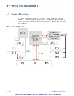
Страница 19: ...CI Express PCIe switch card It provides a PCIe switch function between devices connected to the VPX connector the XMC connectors and a bridging function to PCI PCIX devices connected to the PMC connectors Figure 4 1 Functional Block Diagram Artisan Technology Group Quality Instrumentation Guaranteed 888 88 SOURCE www artisantg com ...

Страница 20: ...e of these ports would normally be expected to be set to Non Transparent mode in this case In addition if the PEX430 has been configured for operation as an XMC carrier the PEX430 acts as a PCIe switch between the SBCs and any PCIe device fitted to the XMC site If the PEX430 had been configured for operation as a PMC carrier the PEX430 would act as a PCIe switch and provide a bridging function to ...

Страница 21: ...e x0 lane x0 lane x0 lane x8 lane x8 lane x0 lane x0 lane x8 lane x4 lane x4 lane x0 lane x8 lane x4 lane x2 lane x2 lane x4 lane x4 lane x4 lane x4 lane Ports can be configured as transparent or non transparent in the following combinations Single transparent port Single non transparent port Single transparent port and single non transparent port By default the PEX430 is configured as 4 ports eac...

Страница 22: ...l to negotiate In this case the PEX430 should be reconfigured to present an 8 lane port or the second 4 lane port should be physically disconnected 4 1 4 PCI Express to PCI PCIX Bridge The PCIe to PCI PCIX bridge function is performed by a PLX PEX8114 The PEX8114 interfaces to the PCIe bus via the PCIe switch with up to 4 PCIe lanes allowing a maximum 2 5 Gbps per lane bit rate The other side of t...

Страница 23: ...configured either by strapping options see below or at power up from data in the EEPROMs If the EEPROMs are blank or if they are in a Hold mode the operation of the PEX8532 and PEX8114 is controlled by options set by the CPLD and jumpers i e strapping If the EEPROMs have valid configuration data and they are not in a Hold mode the operation of the PEX8532 and PEX8114 is controlled by the data prog...

Страница 24: ...X430 are shown in Figure 4 3 The LEDs are highlighted on this diagram in the colour of the LED Additional drawings are included to highlight the individual functions of the LEDs Figure 4 3 LEDs Artisan Technology Group Quality Instrumentation Guaranteed 888 88 SOURCE www artisantg com ...

Страница 25: ... 3 2 PCI Express Switch VPX Connectors Channel A These LEDs indicate the status of some of the PCI Express links between the PCI Express switch and the VPX connectors The LEDs indicated in this diagram correspond to Channel A of the PEX430 Table 4 3 Channel A Width of Link Lanes DS118 DS119 DS120 DS121 On On On On 4 On On 2 On 1 On On 2 with lane reversal On 1 with lane reversal NOTE When the PEX4...

Страница 26: ...iguration Channel B corresponds to the Port 1 When the PEX430 is in a x8 x8 x0 x0 or x8 x4 x2 x2 configuration Channel A and Channel B LEDs are combined to give an indication of the status of the link with a maximum width of 8 NOTE When the PEX430 is in a x8 x8 x0 x0 or a x8 x4 x2 x2 configuration Channel A combined with Channel B corresponds to the Port 0 Table 4 5 Channel A Channel B Width of Li...

Страница 27: ...nectors The LEDs indicated in this diagram correspond to Channel C of the PEX430 Table 4 6 Channel C Width of Link Lanes DS126 DS127 DS128 DS129 On On On On 4 On On 2 On 1 On On 2 with lane reversal On 1 with lane reversal NOTE When the PEX430 is in a x4 x4 x4 x4 configuration Channel C corresponds to Port 2 Artisan Technology Group Quality Instrumentation Guaranteed 888 88 SOURCE www artisantg co...

Страница 28: ...n a x4 x4 x4 x4 configuration Channel D corresponds to Port 3 When the PEX430 is in a x8 x8 x0 x0 configuration Channel C and Channel D LEDs are combined to give an indication of the status of the link with a maximum width of 8 NOTE When the PEX430 is in a x8 x8 x0 x0 configuration Channel C combined with Channel D corresponds to Port 1 Table 4 8 Channel C Channel D Width of Link Lanes DS126 DS127...

Страница 29: ...S130 DS131 DS101 DS102 On On On On On On On On On On On On On On On On 16 On On On On On On On On 8 On On On On 4 On On 2 On 1 On On On On On On On On 8 with lane reversal On On On On 4 with lane reversal On On 2 with lane reversal On 1 with lane reversal 4 3 6 PCI Express Switch XMC Connectors These LEDs indicate the status of the PCI Express links between the PCI Express switch and the XMC conne...

Страница 30: ...100 MHz operation PMC controlled On 66 MHz operation PMC controlled 33 MHz operation PMC controlled On On On 133 MHz operation Configured control On On 100 MHz operation Configured control On On 66 MHz operation Configured control On 33 MHz operation Configured control The alternative function of these LEDs is to indicate which port is being set as the upstream port when changes to the upstream po...

Страница 31: ... board DS140 Vcc 5V Backplane DS141 P12V Backplane only if required by PMC XMC DS142 N12V Backplane only if required by PMC XMC 4 4 Software This board does not have any specific software An associated SBC may require software to enable the in system programming of the EEPROMs 4 4 1 Operating Systems This board does not have an operating system 4 4 2 BIT This board does not have any specific BIT A...

Страница 32: ...ble 5 1 Connector Designations Connector Function P0 Power Supplies and JTAG P1 Channel A D PMC Interrupts P2 PMC XMC I O signals J1 JTAG interface J11 PMC Interface J12 PMC Interface J13 PMC Interface J14 PMC Interface J15 XMC interface J16 XMC interface J17 P3V3 Artisan Technology Group Quality Instrumentation Guaranteed 888 88 SOURCE www artisantg com ...

Страница 33: ...out Table 5 3 J0 Pin Assignment Fin A B C D E F G H I 1 Not Used by product Not Used by product Not Used by product Not Used by product NONE Not Used by product Not Used by product Not Used by product Not Used by product 2 Not Used by product Not Used by product Not Used by product Not Used by product NONE Not Used by product Not Used by product Not Used by product Not Used by product 3 VCC 5V VCC...

Страница 34: ...ND 5 1 4 J1 Backplane Connector Pinout Table 5 5 J1 Pin Assignment Fin A B C D E F G H I 1 CHA_RXOP CHA_RXON GND GND CHA_TXOP CHA_TXON GND GND NOT USED 2 GND GND CHA_RX1P CHA_RX1N GND GND CHA_TX1P CHA_TX1N GND 3 CHA_RX2P CHA_RX2N GND GND CHA_TX2P CHA_TX2N GND GND NOT USED 4 GND GND CHA_RX3P CHA_RX3N GND GND CHA_TX3P CHA_TX3N GND 5 CHB_RXOP CHB_RXON GND GND CHB_TXOP CHB_TXON GND GND SYS_CON 6 GND G...

Страница 35: ... 5 1 6 J2 Backplane Connector Pinout Table 5 7 J2 Pin Assignment Fin A B C D E F G H I 1 IO1N IO1P GND GND IO0N IO0P GND GND SINGIO0 2 GND GND IO3N IO3P GND GND IO2N IO2P GND 3 IO5N IO5P GND GND IO4N IO4P GND GND SINGIO1 4 GND GND IO7N IO7P GND GND IO6N IO6P GND 5 IO9N IO9P GND GND IO8N IO8P GND GND SINGIO2 6 GND GND IO11N IO11P GND GND IO10N IO10P GND 7 IO13N IO13P GND GND IO12N IO12P GND GND SIN...

Страница 36: ...criptions Signal Description Type CHA D_RX0 3N PCI Express receive lane 0 of channel A D Negative signal of differential pair Input CHA D_RX0 3P PCI Express receive lane 0 of channel A D Positive signal of differential pair Input CHA D_TX0 3N PCI Express transmit lane 0 of channel A D Negative signal of differential pair Output CHA D_TX0 3P PCI Express transmit lane 0 of channel A D Positive signa...

Страница 37: ...ignment Pin Signal 1 VPX_JTAG_TRST 2 GND 3 VPX_JTAG_TDO 4 GND 5 VPX_JTAG_TDI 6 GND 7 VPX_JTAG_TMS 8 GND 9 VPX_JTAG_TCK 10 GND 5 1 11 J17 Connector Table 5 12 J17 Pin Assignment Pin A 1 P3V3 2 P3V3 Artisan Technology Group Quality Instrumentation Guaranteed 888 88 SOURCE www artisantg com ...

Страница 38: ...3 PMC_AD 25 24 GND 25 GND 26 PMC_C_BE3 27 PMC_AD 22 28 PMC_AD 21 29 PMC_AD 19 30 VCC 31 P3V3 32 PMC_AD 17 33 PMC_FRAME 34 GND 35 GND 36 PMC_IRDY 37 PMC_DEVSEL 38 VCC 39 PMC_PCIX_CAP 40 PMC_LOCK 41 PMC_SDONE 42 PMC_SBO 43 PMC_PAR 44 GND 45 P3V3 46 PMC_AD 15 47 PMC_AD 12 48 PMC_AD 11 49 PMC_AD 9 50 VCC 51 GND 52 PMC_C_BE0 53 PMC_AD 6 54 PMC_AD 5 55 PMC_AD 4 56 GND 57 P3V3 58 PMC_AD 3 59 PMC_AD 2 60 ...

Страница 39: ..._AD 26 23 PMC_AD 24 24 P3V3 25 PMC_IDSEL 26 PMC_AD 23 27 P3V3 28 PMC_AD 20 29 PMC_AD 18 30 GND 31 PMC_AD 16 32 PMC_C_BE2 33 GND 34 XSIG040596 35 PMC_TRDY 36 P3V3 37 GND 38 PMC_STOP 39 PMC_PERR 40 GND 41 P3V3 42 PMC_SERR 43 PMC_C_BE1 44 GND 45 PMC_AD 14 46 PMC_AD 13 47 PMC_M66EN 48 PMC_AD 10 49 PMC_AD 8 50 P3V3 51 PMC_AD 7 52 XSIG040598 53 P3V3 54 XSIG040600 55 PMC_MSCL_IPMI_CLK 56 GND 57 PMC_MSDA_...

Страница 40: ... 23 PMC_AD 55 24 PMC_AD 54 25 PMC_AD 53 26 GND 27 GND 28 PMC_AD 52 29 PMC_AD 51 30 PMC_AD 50 31 PMC_AD 49 32 GND 33 GND 34 PMC_AD 48 35 PMC_AD 47 36 PMC_AD 46 37 PMC_AD 45 38 GND 39 P3V3 40 PMC_AD 44 41 PMC_AD 43 42 PMC_AD 42 43 PMC_AD 41 44 GND 45 GND 46 PMC_AD 40 47 PMC_AD 39 48 PMC_AD 38 49 PMC_AD 37 50 GND 51 GND 52 PMC_AD 36 53 PMC_AD 35 54 PMC_AD 34 55 PMC_AD 33 56 GND 57 P3V3 58 PMC_AD 32 5...

Страница 41: ...1N 13 PMC_IO6P 45 PMC_IO22P 14 PMC_IO7P 46 PMC_IO23P 15 PMC_IO6N 47 PMC_IO22N 16 PMC_IO7N 48 PMC_IO23N 17 PMC_IO8P 49 PMC_IO24P 18 PMC_IO9P 50 PMC_IO25P 19 PMC_IO8N 51 PMC_IO24N 20 PMC_IO9N 52 PMC_IO25N 21 PMC_IO10P 53 PMC_IO26P 22 PMC_IO11P 54 PMC_IO27P 23 PMC_IO10N 55 PMC_IO26N 24 PMC_IO11N 56 PMC_IO27N 25 PMC_IO12P 57 PMC_IO28P 26 PMC_IO13P 58 PMC_IO29P 27 PMC_IO12N 59 PMC_IO28N 28 PMC_IO13N 60...

Страница 42: ...IO13P B7 27 PMC_IO12N E7 28 PMC_IO13N A7 29 PMC_IO14P H8 30 PMC_IO15P D8 31 PMC_IO14N G8 32 PMC_IO15N C8 33 PMC_IO16P F9 34 PMC_IO17P B9 35 PMC_IO16N E9 36 PMC_IO17N A9 37 PMC_IO18P H10 38 PMC_IO19P D10 39 PMC_IO18N G10 40 PMC_IO19N C10 41 PMC_IO20P F11 42 PMC_IO21P B11 43 PMC_IO20N E11 44 PMC_IO21N A11 45 PMC_IO22P H12 46 PMC_IO23P D12 47 PMC_IO22N G12 48 PMC_IO23N C12 49 PMC_IO24P F13 50 PMC_IO2...

Страница 43: ...MC_CHA_RX6P XMC_CHA_RX6N Not Used XMC_CHA_RX7P XMC_CHA_RX7N Not Used 18 GND GND Not Used GND GND Not Used 19 BP_REF_CLK_P BP_REF_CLK_N Not Used XMC_WAKE XMC_ROOT0 Not Used 5 1 18 J16 XMC Connector Table 5 19 J16 Pin Assignment Pin A B C D E F 1 XMC_IO0P XMC_IO0N XMC_IO20P XMC_IO1P XMC_IO1N XMC_IO21P 2 GND GND XMC_IO20N GND GND XMC_IO21N 3 XMC_IO2P XMC_IO2N XMC_IO22P XMC_IO3P XMC_IO3N XMC_IO23P 4 G...

Страница 44: ...IO16P F9 C17 XMC_SINGIO8 RSVD E17 XMC_IO17N A9 A18 GND GND C18 XMC_SINGIO10 RSVD E18 GND GND A19 XMC_IO18P H10 C19 XMC_SINGIO12 RSVD E19 XMC_IO19N C10 B1 XMC_IO0N E1 D1 XMC_IO1P B1 F1 XMC_IO21P B11 B2 GND GND D2 GND GND F2 XMC_IO21N A11 B3 XMC_IO2N G2 D3 XMC_IO3P D2 F3 XMC_IO23P D12 B4 GND GND D4 GND GND F4 XMC_IO23N C12 B5 XMC_IO4N E3 D5 XMC_IO5P B3 F5 XMC_IO25P B13 B6 GND GND D6 GND GND F6 XMC_I...

Страница 45: ...input voltages or apply reversed bias to the assembly If such conditions occur toxic fumes may be produced due to the destruction of components A 1 3 Max Current 3 3 A Meets MIL STD 416D CE101 4 and CE102 Transient suppression to MIL STD 704D option to meet MIL STD 1275A available A 2 Interface Specifications PEX430 meets the following interface specifications VITA 46 0 VITA 46 4 Artisan Technolog...

Страница 46: ... PEX430 10000 The predictions are carried out using MIL HDBK 217F Notices 1 and 2 parts count method To complement the 217 failure rates some manufacturers data is included where appropriate Q values have been modified according to industry practice Table A 1 Reliability MTBF Environment Fail Rate FPMH MTBF Hours Ground Benign 30 C 2 3247328 430 157 Ground Fixed 40 C 5 474254 182 673 Ground Mobile...

Страница 47: ...erature rugged cooled by forced air Conformal coated for additional protection A 5 2 Conduction cooled Boards Table A 3 Environmental Specifications Conduction cooled Boards Build style Temperature c Low pressure feet Vibration Shock Humidity salt fog Comments Rugged Conduction cooled Level 4 Operating 40 to 75 at the thermal interface Storage 50 to 100 Shock 10 C minute over range Operating 70 00...

Страница 48: ...ode Information PEX430 B M X Y Mechanics 1 0 8 pitch VITA 46 Reserved Mezzanine P PMC X XMC Build level 1 Build level 1 2 Build level 2 3 Build level 3 4 Build level 4 5 Build level 5 Erratum December 2010 Artisan Technology Group Quality Instrumentation Guaranteed 888 88 SOURCE www artisantg com ...

Страница 49: ...Number 10 F Flammability 7 H Heatsink 8 I Inspection 11 J JTAG 17 Jumpers 13 L Label 10 LEDs 23 M MTBF 45 P PCI Express Port 20 PCI Express Switch 21 Power Requirements 44 Problems 8 Product Code 47 Product Identification 10 R Recovery Mode 22 Related Documents 8 Reliability 45 Revision State 10 S Safety Notices 7 Signal Descriptions 35 T Technical Support Contact Details 8 W Websites 8 Weight 45 ...

Страница 50: ...S WITH NO REPRESENTATIONS OR WARRANTIES OF ANY KIND WHETHER EXPRESS OR IMPLIED INCLUDING BUT NOT LIMITED TO WARRANTIES OF DESIGN MERCHANTABILITY OR FITNESS FOR A PARTICULAR PURPOSE ALL OTHER LIABILITY ARISING FROM RELIANCE ON ANY INFORMATION CONTAINED HEREIN IS EXPRESSLY DISCLAIMED Abaco Systems Information Centers Americas 1 866 652 2226 866 OK ABACO Europe Middle East and Africa 44 0 1327 359444...

Страница 51: ...l service in house repair center WE BUY USED EQUIPMENT Sell your excess underutilized and idle used equipment We also offer credit for buy backs and trade ins www artisantg com WeBuyEquipment REMOTE INSPECTION Remotely inspect equipment before purchasing with our interactive website at www instraview com LOOKING FOR MORE INFORMATION Visit us on the web at www artisantg com for more information on ...

Отзывы: