


Installation
Configuring the CEI-100
CEI-100/CEI-200/CEI-
x20 User’s Manual
33
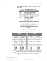
CEI-100 Base I/O Address
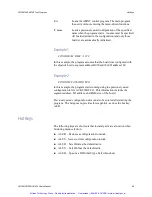
Switches 7 through 10 set the base I/O address for the CEI-100. The
following example demonstrates the default address of 380 (hex).
Table 29. Default Address of 380 (hex) Example
Switch Position
-
-
-
7
8
9
10
-
-
-
Address Bit
9
8
7
6
5
4
3
2
1
0
Switch Setting
-
-
-
On
On
On
On
-
-
-
Base address
1
1
1
0
0
0
0
0
0
0
Hex value
3
8
0
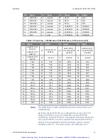
Other sample settings for switches 7 through 10 respectively generate the
following base I/O addresses:
388
= On On On Off
390
= On On Off On
398
= On On Off Off
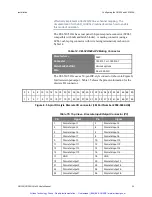
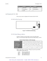
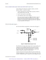
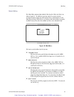
CEI-100 Interrupts and Slew rate
Jumper block JP1, located in the lower right corner of the board, sets the
host interrupt level and the ARINC transmit data slew rate. With no
jumpers in place, there is no host interrupt enabled, and the slew rate is set
for the high (100Kbs) bit rate. To enable an interrupt, select one of the
three interrupt levels (IRQ3, IRQ4, or IRQ5) and install its jumper. For
example, a jumper between locations 1 and 2 enables interrupts on IRQ3.
Interrupts are not required for normal operation of the board. To set the
correct slew rate for the transmit channel to work at the low (12.5Kbs) bit
rate, connect two jumpers – one between locations 7 and 8 and the other
between locations 9 and A.
Table 30. Jumper block JP1
JP1
IRQ3
IRQ4
IRQ5
Slew rate
2
4
6
8
10
1
3
5
7
9
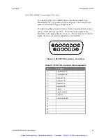
PC bus connector
Artisan Technology Group - Quality Instrumentation ... Guaranteed | (888) 88-SOURCE | www.artisantg.com


