


Description of CEI-100/200 ARINC Interface
Controlling the Timers
CEI-100/CEI-200/CEI-
x20 User’s Manual
162
Controlling the Timers
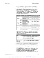
The ARINC boards have an on-board timer mechanism. The timer rate is
determined by a programmable value, which is written at the timer control
location:
CEI-100 -
044Ch
CEI-200 -
0494h
To determine what timer value to use, see AR_SET_TIMERRATE. Each
time a timer “tick” occurs on the ARINC board, a 4-byte timer count
variable is incremented (see AR_GET_TIMERCNT) which is maintained
at the offset:
CEI-100 -
0448h
CEI-200 -
049Ah
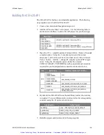
Selecting the Receive Modes
There are three modes of ARINC data storage (see
AR_SET_STORAGE_MODE). On the CEI-200, this is programmed with
the storage mode control word at location:
04E0h
where 0 = buffered mode, 1 = dedicated mode and 2 = merged mode.
On the CEI-100, this is programmed with the slave status word at location:
0464h
where bits 3 and 4 define the mode: 0 = buffered mode, 1 = dedicated
mode and 2 = merged mode. This word contains other data that must
be maintained when updating these bits.
Enabling Time Tags
Timetags can be enabled or disabled (see AR_TIMETAG_CONTROL.)
On the CEI-200 this is programmed using the timetag control word at
location:
04DEh
where 0 = do not store timetags and 1 = store time tags.
Artisan Technology Group - Quality Instrumentation ... Guaranteed | (888) 88-SOURCE | www.artisantg.com


