☛
PAGE
2 9
2 9
!
☛
ROUTING
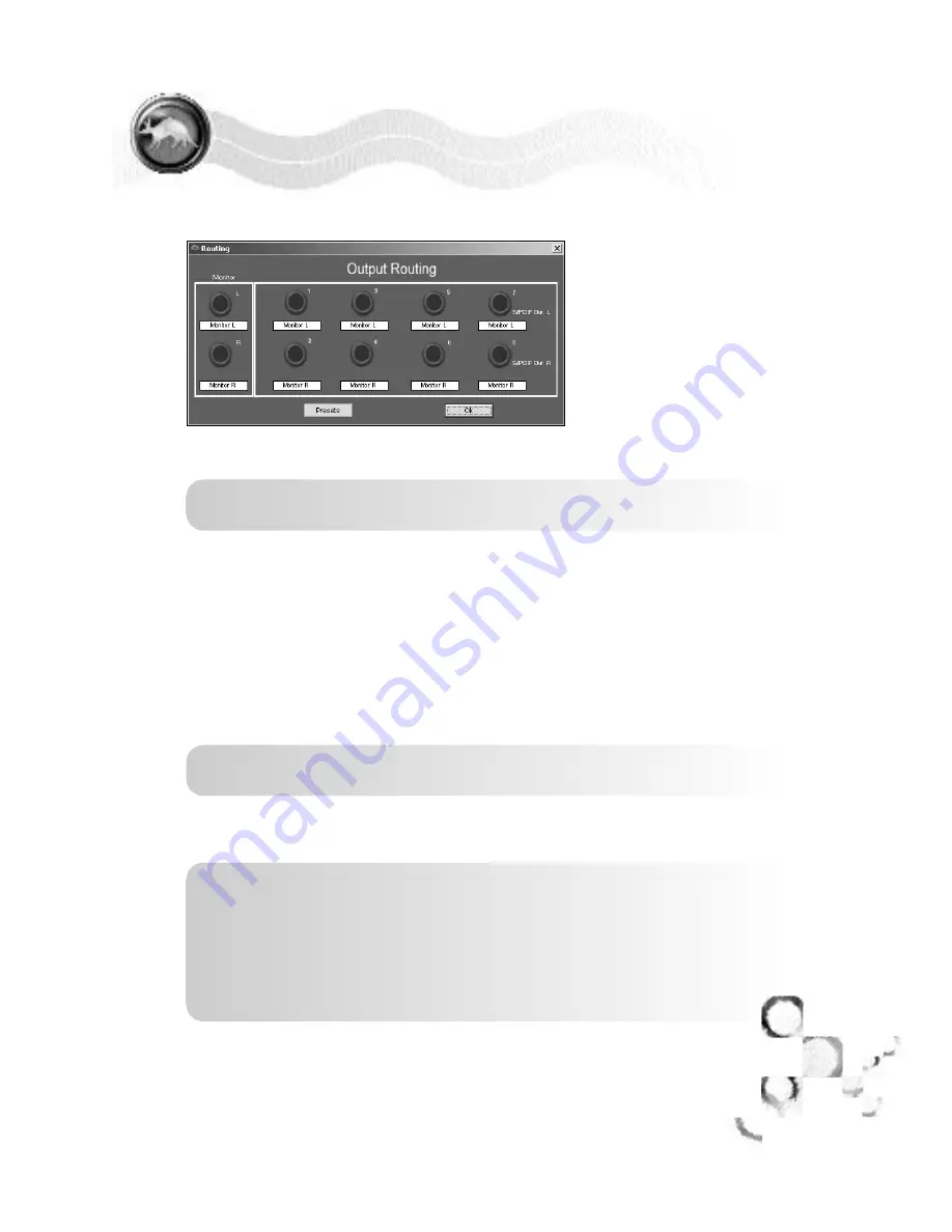
The Routing section allows
you to control what signals
are sent to each output on
the back of the Q10. A
picture of the Q10 outputs is
provided, with a menu
beneath each output. Double
click a menu to access a list
of signal paths that can be
routed to an output.
NOTE: Whatever is routed to outputs 7 & 8 will be routed to the S/PDIF
output as well
If Analog Input 1-8 is selected, the output will only monitor the
incoming signal of the input assigned to it.
If Playback 1-8 is selected, the output will only monitor playback tracks
from audio software routed to that playback channel.
If Monitor L or Monitor R is selected, the output will monitor all
playback tracks, and all inputs.
If Tone is selected, the output will generate a 1khz test tone, allowing
you to verify your hardware is working.
IMPORTANT: This tone is rather loud. To avoid a nasty surprise, Turn
down your speaker volume before assigning tone to an output.
If Silence is selected, nothing but digital silence will come out of the
output. This is useful for system calibration and other diagnostics.
NOTE: Most users will have output L, R set to monitor L, R. This is the
output of the Control Panel Mixer, and will always be monitoring the 10
physical inputs and the 10 playback channels.
Additionally, it is common to have Outputs 1-8 assigned to playback 1-8
respectively. This directly links these tracks in the recording software to
the physical outputs of the Q10 allowing you to send the signals from
these outputs to any outboard analog gear for processing or mixing.
Q10
SOFTWARE
Q10 CONTROL PANEL
ROUTING
DIRECT PRO Q10
O W N E R S M A N U A L
Содержание Direct Pro Q10
Страница 2: ...MANUAL REVISION 1 5 ...
Страница 3: ......
Страница 5: ......
Страница 26: ...PAGE 2 1 2 1 Q10 CONNECTION DIAGRAM DIRECT PRO Q10 O W N E R S M A N U A L ...
Страница 27: ...PAGE 2 2 2 2 Q10 CONNECTION NOTES DIRECT PRO Q10 O W N E R S M A N U A L ...


